background image

16

TECHNICAL PASSPORT. INSTALLATION and OPERATION MANUAL

TECHNICAL PASSPORT. INSTALLATION and OPERATION MANUAL

TECHNICAL PASSPORT. INSTALLATION and OPERATION MANUAL

TECHNICAL PASSPORT. INSTALLATION and OPERATION MANUAL

should  be  coated  with  a  thick  layer  of 

thermal  paste  and  inserted  into  the 

sensor sleeve to the full depth. If the fit is 

too loose, slide a piece of copper plate or 

wire in beside the sensor, Seal the sensor 

sleeve  opening  with  silicone  sealant 

to  prevent  water  ingress.  Ensure  that 

sensors  used  on  the  collector  are  high 

temperature rated (up to 250°C/486°F), in 

particular the cable.

7.5.  Mounting  of  Safety  temperature 

valve

It is recommended, and may be required 

by regulations, that a temperature control 

device  (safety  tempetarure  value)  be 

fitted  into  the  hot  water  pipe  between 

the  water  heater  and  bathrooms  and 

en-suites  to  reduce  the  risk  of  scalding. 

This is achieved by controlling the water 

temperature  to  below  50°C/122°F 

(temperature may be adjustable).

7.6.  Pressure control. Temperature 

control. Relief valve.

Regardless 

of 

the 

installation 

configuration,  pressure  release  values, 

expansion vessels and/or other pressure 

control  devices  must  be  installed.  The 

solar loop should be designed to operate 

at  no  more  than  800kPa  - 

PRV may be 

850kPa. (800kPa = 8bar = 116psi)

For  installation  where  mains

  pressure 

water  is  used,  the  system  should  ideally 

be  designed  to  operate  at  a  pressure  of 

<500 kPa,


achieved by use of a pressure 

limiting/reduction value.

For the reliable operation of system, we 

recommend  you  check  the  lever  of  the 

pressure  and  temperature  return  valve 

(PTRV) every six months. The PTRV lever 

should  be  raised  and  dropped  gently 

without effort.

Collector  working  (operating)  pressure 

should be secured using a pressure relief 

valve at 6 bars.

An expansion vessel must be mounted in 

order to take up the extra volume of fluid 

caused by heat expansion. Recommended 

capacity of expansion vessel is 4 ÷ 5 L/m

2


of PK type collector area, and 8 ÷ 10 L/m

2


of VTC type collector area.

To  avoid  damage  to  system  and  heat 

carrier  circuit,  all  air  purge  valves  must 

be  closed  upon  purging  of  air  from  the 

system. This will prevents the release of 

steam  and  the  penetration  of  oxygen 

from the ambient air.

7.7. Filling of system.

To  prevent  overheating,  the  filling 

of  system  must  be  carried  out  in  the 

morning  or  evening  in  the  absence  of 

direct sunlight.

Direct  use  of  collector  for  hot  water 

preparation is not allowed because of the 

eventual  clogging  of  pipes  over  a  short 

time by limescale deposits.


Inside collector pipes and risers circulates 

a certain fluid (water, propylene glycol or 

Tyfocor  of  freezing  point  corresponding 

to the requirements of certain installation 

(see  section  7.1  of  this  manual.)When 

using any other heat carrier fluid to fill the 

collector manufacturer does not take any 

responsibility for product warranty.

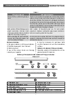
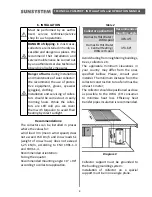
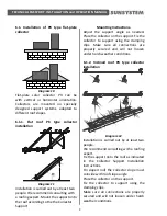
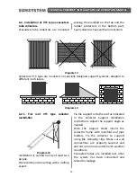
Summary of Contents for PK 2.0

Page 1: ...TECHNICAL PASSPORT INSTALLATION and OPERATION MANUAL model serial number SUNSYSTEM solar collectors FLAT PLATE COLLECTOR series EVACUATED TUBE COLLECTOR VTC series v0 1...

Page 2: ...t transfer plates 6 4 Transportation of the collector 6 5 Delivery of the collector 6 6 Installation 8 6 1 Installation of flat plate collector 9 6 2 Installation of evacuated tube collector VTC 10 6...

Page 3: ...uring installation and operation the country specific requirements and regulations must be observed local construction regulations on installation on building mass of the system to comply with the bui...

Page 4: ...port the heating system only in the manner described in this manual Installation and maintenance must be performed by a technician service shop authorized for such operations 2 DESCRIPTION OF PK TYPE...

Page 5: ...y has the necessary constructive strength to withstand the year round whims of weather not sacrificing on light weight 3 DESCRIPTION OF VTC TYPE EVACUATED TUBE COLLECTOR 3 1 Evacuated tube Absorber co...

Page 6: ...e use of pallet jack fork truck or other hoisting devices is a must Transportation of Flat plate collectors PK Protective plastic corners are fit on each panel collector frame to protect it from rubbi...

Page 7: ...ectors before connecting collectors to system Before installing PK type collectors remove the protective plastic cor ners from collector frames Do not take out or expose the tubes to sunlight during i...

Page 8: ...n be installed in places where the values for wind load Vm mean wind speed does not exceed 150 km h and snow loads Sk weight of snow mass does not exceed 1 25 kN m according to ENV 1991 1 3 and 1991 1...

Page 9: ...Adjust the support angle as needed Place the collector on the support Fix the collector to support using the clamping clips Make sure all connections are properly secured and will not loosen under ha...

Page 10: ...slopes Diagram 14 6 2 1 Flat roof VTC type collector installation Diagram 15 Installation is carried out by at least two people We recommend consulting with a roofing expert Fix the support onto the...

Page 11: ...e the bar rests on the roof tile Install the two side rails F to fixing straps B Use the screws and therefore provided orifices in the rails Diagram 17 Step 3 At the bottom of both side rails F insert...

Page 12: ...box The upper end of the tube with a silver probe like tip as must fit in the manifold nest The lower end of the tube must pass through tube holder D Place the plastic protector on the bottom of tube...

Page 13: ...service shop for such operations Our warranty does not cover dam age from extremely strong acts of nature We recommend that dam age of collectors be included as a clause in your building insurance Co...

Page 14: ...ary in the summer period In this case we recommend that the system be fitted with a device for heat dissipation or to add more users to the hot water circuit in the summer swimming pool or other simil...

Page 15: ...o increase in temperature until the limit of the temperaure relief valve is reached at which point hot water will be dumped from the system If a PTRV is not installed on the collector steam will form...

Page 16: ...ed to operate at a pressure of 500 kPa achieved by use of a pressure limiting reduction value For the reliable operation of system we recommend you check the lever of the pressure and temperature retu...

Page 17: ...d OPERATION MANUAL 7 8 Connection diagrams Diagram 25 Connection of Flat plate collector K to solid fuel boiler WBS combi tank KSC2 and three way valve Must be performed by an autho rized service tech...

Page 18: ...SSPORT INSTALLATION and OPERATION MANUAL TE TECHNICAL PASSPORT INSTALLATION and OPERATION MANUAL TE Diagram 26 Connection of Evacuated tube collector VTC to solid fuel boiler WBS combi tank KSC2 and t...

Page 19: ...19 AL TECHNICAL PASSPORT INSTALLATION and OPERATION MANUAL Diagram 27 Connection of Flat plate collector K to solid fuel boiler WBS solar water tank SON buffer tank P and three way valve...

Page 20: ...INSTALLATION and OPERATION MANUAL TE TECHNICAL PASSPORT INSTALLATION and OPERATION MANUAL TE Diagram 28 Connection of Flat plate collector K to solid fuel boiler WBS solar water tank SON buffer tank...

Page 21: ...g pressure pump operation hydraulic connections Checkup of heat carrier fluid replacement thereof 9 2 Cleaning of collectors from dust deposits fallen dry leaves and twigs Keeping the collector surfac...

Page 22: ...tion unsuitable or incorrect use Failure to observe the installation use and maintenance instructions set forth in the installation manual of respective product Improper installation or use as well as...

Page 23: ...mediate replacement of the product he has claimed warranty for before receiving the decision as to the claim said request shall be accompanied by a Purchase requisition from the Commercial Department...

Page 24: ...e Mpa 0 6 Inlet Outlet N P R1 2 Inlet Outlet New Line N P Cu 22 Heat carrier flow rate l m2 h 50 Weight kg 33 38 31 33 36 38 Thickness of solar glass mm 4 2 Material of solar glass K Heat tempered pri...

Page 25: ...chnical features of VTC type Evacuated tube collector Diagram 30 Elements of VTC type Evacuated tube collector 1 Manifold 2 Inlet Outlet sleeve 3 Evacuated glass tube 4 Holder and protector of evacuat...

Page 26: ...tant plastic RAL 9005 Heat carrier pipes material type Copper Heat pipe TU 1 Coating of absorber Selective coating Manifold unit box material insulation Anodized aluminum Polyurethane foam 30 mm Effic...

Page 27: ...ntal protection regulation 12 2 Recycling and waste disposal At the end of life cycle of each product its components are due to be disposed of in conformity with regulatory prescriptions According to...

Page 28: ...garia t 359 54 874 555 f 359 54 874 556 e mail ftrade sunsystem bg 129 Vitosha Blvd 1000 Sofia Bulgaria t 359 02 952 24 05 f 359 02 952 67 20 e mail sunsofia sunsystem bg www sunsystem bg ISO 9001 200...

Reviews: