background image

Page 2

Dear SunBriteTV Customer:
Congratulations on the ownership of Model 2220HD all-weather outdoor LCD TV, and welcome to the family of satisfied SunBrite customers. You are in great company 
with thousands of homeowners and esteemed commercial facilities such as Yankee Stadium, Fenway Park,  Disney World, and Sea World who have trusted us to deliver 
superior performance, lasting durability and the enjoyment of superb television viewing in the great outdoors. 
With a traditional sense of customer satisfaction and attention to detail, our products are designed to withstand the rigors of the outdoor environment and provide our 
customers with many years of optimum viewing. 
To ensure safety and long product life, please read the Important Safety Instructions and complete manual carefully before using the TV. If you have any questions about 
the installation procedures, please contact our qualified SunBriteTV Customer Support Team at 800.331.4626.

IMPORTANT SAFETY INSTRUCTIONS

WARNING: 

 TV must be plugged into a GFCI receptacle. 

TV and GFCI  RECEPTACLE MUST BE INSTALLED NO LESS THAN 5 FEET FROM ANY BODY OF WATER (SUCH 

AS POOL OR SPA). Check local  building codes for proper installation guidelines.

This product utilizes tin-lead solder, and fluorescent lamp containing a small amount of mercury. Disposal of these ma-

terials may be regulated due to environmental considerations. For disposal or recycling information, please contact your local 

authorities or the Electronic Industries Alliance: www.eia.org. 

WARNINg: This unit is equipped with a 3-pin grounded plug. The plug will only fit into a grounded power outlet. This is a safety feature. If you 

are unable to insert the plug into the outlet, contact your electrician. Do not alter this plug, as this will defeat the safety feature.

WARNINg: The main plug is used as the disconnect device and shall remain readily operable.

WARNINg: This product shall be connected to a mains socket outlet with a protective earthing connection.

CAUTION: TO PREVENT ELECTRIC SHOCK, MATCH WIDE BLADE OF PLUG TO WIDE SLOT, FULLY INSERT.
WARNINg: FCC Regulations state that any unauthorized changes or modifications to this equipment not expressly approved by the manufac-

turer could void the user’s authority to operate this equipment.

NOTE TO CATV SYSTEM INSTAllER: This reminder is provided to call the CATV system installer’s attention to Article 820-40 of the National 

Electrical Code that provides guidelines for proper grounding and, in particular, specifies that the cable ground shall be connected to the 

grounding system of the building, as close to the point of cable entry as practical.

WARNINg: To reduce the risk of fire or electric shock, do not expose the inside of this apparatus to rain or moisture. 

Important Safety Instructions

1) Read these instructions, and keep them for future use. 
2) Heed all warnings and follow all instructions. 
3) Do not block any ventilation openings. Install in accordance with the manufacturer’s instructions.
4) Do not install near any heat sources such as radiators, heat registers, stoves, or other apparatus (including amplifiers) that 

produce heat.
5) Do not defeat the safety purpose of the polarized or grounding-type plug. A polarized plug has two blades with one wider than 

the other. A grounding type plug has two blades and a third grounding prong. The wide blade or the third prong are provided for 

your safety. If the provided plug does not fit into your outlet, consult an electrician for replacement of the obsolete outlet.
6) Protect the power cord from being walked on or pinched particularly at plugs, convenience receptacles, and the point where 

the cord exits from the apparatus.
7) Only use attachments/accessories specified by the manufacturer.
8) Use only the cart, stand, tripod, bracket or table specified by the manufacturer, or 

 sold with the apparatus. When a cart is used, use caution when moving the cart/apparatus 

combination to avoid injury from tip-over.
9) Unplug this apparatus during lightning storms.
10) Refer all servicing to qualified service personnel. Servicing is required when the apparatus has been damaged in any way, 

such as  power-supply cord or plug is damaged, liquid has been spilled or objects have fallen into the apparatus, does not operate 

normally, or has been dropped.

Disclaimer: 

While SunBriteTV LLC intends to make this manual accurate and complete, we do not make claims that the information 

contained within covers all details, conditions or variations, nor does it provide for every possible contingency in connection with the 

installation or use of this product. The information contained in this manual may change without notice.

Summary of Contents for SB-2220HD

Page 1: ...Operator s Manual Model SB 2220HD Rev 2220HD Rev318 120801 PN M22 001 01 All Weather Outdoor LCD Television ...

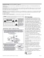
Page 2: ...he user s authority to operate this equipment Note to CATV system installer This reminder is provided to call the CATV system installer s attention to Article 820 40 of the National Electrical Code that provides guidelines for proper grounding and in particular specifies that the cable ground shall be connected to the grounding system of the building as close to the point of cable entry as practic...

Page 3: ...nable protection against harmful interference in a residential installation This equipment generates uses and can radiate radio frequency energy and if not installed and used in accordance with the instructions may cause harmful interference to radio communications However there is no guarantee that interference will not occur in a particular installation If this equipment does cause harmful inter...

Page 4: ... SunBriteTV will resist water exposure from normal rain sprinklers garden hoses etc However it is not designed to withstand pressure washers high pressure water jets or hurricane type weather Do not service SunBriteTV yourself Removal of the television screen cover may expose you to high voltage or other dangerous risks Refer all servicing to a qualified service professional Warranty will not be h...

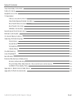
Page 5: ...ns Side Panel and Front Panel Controls Remote Control Guide On Screen Display Controls Adjusting On Screen Displays Picture Menu Sound Menu Setting Menu Channel Menu Trouble Shooting Care of SunBriteTV Specifications Features Information and Instructions Extreme Climate Warning Programming Other Manufacturers Universal Remote Control Devices SunBriteTV Pixel Quality Policy Appendix A RS232 Control...

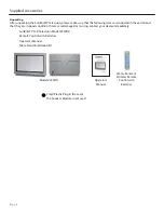
Page 6: ...at they are in good condition If items are damaged or missing contact your dealer immediately SunBriteTV LCD Television Model 2220HD Remote Control with Batteries Operator s Manual Table Stand Installation Kit Water Resistant Wireless Remote Control with Batteries Model 2220HD Operator s Manual Small Plastic Plug in the event the Speaker Module is removed ...

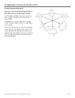
Page 7: ...irect sunlight Ideal placement is in an area where the TV is shaded by trees landscape and or structures or under a patio cover or gazebo If the sun shines directly on the screen for long periods of time dark areas may develop on the screen This is a normal reaction for the LCD panel and will not cause damage to the screen Either turn the screen away from the sun or apply shade to the TV and the d...

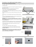
Page 8: ...at attach the Speaker Module to the TV Figure 2 WARNING Always replace Speaker Module Mounting Screws Failure to do so will allow water to seep inside your TV This can cause serious injury and can damage your TV 4 Gently remove the Speaker Module away from the TV Note that the Speaker Module Cable Connector is connected to the TV Cable Connector Figure 3 5 Disconnect the Speaker Module Cable Conne...

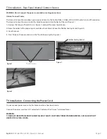
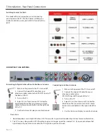
Page 9: ...y Thumb Screws Figure 1 and pull the cover towards you 2 Route the cables to the proper inputs and place the cable cords over the Rubber Sealing Gasket Figure 2 3 Close the cover 4 Press firmly on the cover and screw the Thumb Screws tightly Figure 3 Figure 1 Figure 2 Figure 3 Rubber Sealing Gasket Thumb Screws TV Installation Connecting the Power Cord Do not connect power cord until all cable con...

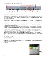
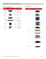
Page 10: ...o Use the Source Button to select YPbPr1 to review this connection 8 COMPONENT 2 Upper his connection ports are for DVD players or satellite cable set top boxes that use component cables From left to right connect green blue and red for video and then connect white for left channel audio red for right channel audio Use the Source Button to select YPbPr2 to review this connection 9 AV 1 CVBS or S V...

Page 11: ...SunBriteTV Model SB 2220HD Operator s Manual Page 11 TV Installation Rear Panel Connections Red Green Blue Yellow Green Red White Connection Descriptions Cable Descriptions ...

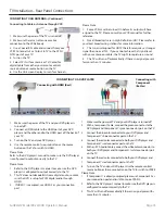
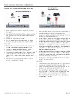
Page 12: ...Screen Display to scan for channels Connecting to Digital Cable without Cable Box or Antenna Connecting to Cable or Antenna 1 Make sure the power of the TV is turned off 2 Connect the Coaxial RF cable from your antenna or cable to the ATSC NTSC port off the back of the TV 3 Turn on the TV 4 Select TV Air for antenna or TV Cable for cable from either your remote control s source button or source bu...

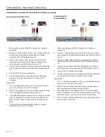
Page 13: ...he source button on the TV to switch to HDMI Please Note Refer to the DVD player s manual to make sure the DVD player is configured to output correctly to the TV 1 Make sure the power ofTV and your DVD player is turned off 2 With a Component Cable connect the green connector to the DVD player and Component 1 s green connector port on theTV 3 Connect the blue color connector to your DVD player and ...

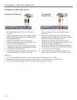
Page 14: ...er is turned off 2 Obtain a Yellow Video Cable Connect the Yellow Video connector to both your DVD player and Composite s Yellow Video connector port off the back of your TV 3 Obtain a RCA Audio Cable Connect the white color connector to both your DVD player and Composite s white connector port off the back of your TV 4 Connect the red color connector to both your DVD player and Composite s red co...

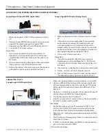
Page 15: ... off the back of your TV 3 Connect the blue color connector to both your set top box and Component 1 s blue connector port off the back of your TV 4 Connect the red color connector to both your set top box and Component 1 s red connector port off the back of your TV 5 Obtain a RCA Audio Cable Connect the white color connector to both your set top box and Component 1 s white connector port off the ...

Page 16: ... up SONY s codes in your universal remote s hand book 4 This TV will turn off automatically if there s no signal present for more than 15 minutes 1 Make sure the power of the TV and your set top box is turned off 2 Connect a Yellow Video connector to both your set top box and Composite s Yellow Video connector port off the back of your TV 3 Connect a white color connector to both your set top box ...

Page 17: ...lease Note 1 For the best picture set your PC resolution to 1920 x 1080 at 60 Hz Refer to the PC or graphic card manual for further instructions on how to set your resolution and refresh rate 2 Refer to your PC manual for video output requirements of the video card 3 The TV will turn off automatically if there s no signal present for more than 15 minutes 4 If HDMI 1 is already occupied use HDMI 2 ...

Page 18: ...our PC manual for video output requirements of the video card 4 The VGA port of the TV features a power saving mode which will automatically turn off the TV if there is no signal provided for more than 15 minutes CONNECTING TO A PC Continued IR Emitter Installation To install the IR Emitter The photo to the right shows an IR Emitter installed The end of the Emitter is to be mounted in front of the...

Page 19: ... In OSD menu both keys are used to navigate within menu Vol is used to select the highlighted options IR Sensor Connect the power cord to a GFCI protected AC outlet with in use waterproof cover Warning TV must be installed at least 5 feet away from standing water such as but not limited to a pool or spa Connecting the Power Cord WARNING TV AND GFCI RECEPTACLE MUST BE INSTALLED AT LEAST 5 FEET AWAY...

Page 20: ...els directly R Returns to the previous channel FREEZE Freezes the TV picture Press the button again to unfreeze the picture SLEEP Sets time for the TV to turn Off CC Selects Closed Caption CC only works under sources TV AV1 and AV2 V Functions the Volume Up V Functions the Volume Down MUTE Mutes the TVs Audio MENU Opens Exits the TV menu CH Functions the Channel Up CH Functions the Channel Down MT...

Page 21: ...ttings This menu manages Parental Controls Time Closed Caption Menu Settings Language and Transparency Channel This menu manages Channel functions such as Scanning Channels Editing Channels Checking Signal Strength etc Your TV has been factory set to plug in and enjoy your programming In the event you turn on the TV and get the message Please run Channel Auto Scan press your remote s Menu button p...

Page 22: ... to adjust the sharpness level of picture Advanced Video see below Press qp buttons to Advanced Video then use t u to adjust the selections for Color Temper Zoom Mode Noise Reduction and Overscan and Adaptive Contrast 1 Press qp buttons to move the cursor to the item to be selected 2 Press t u buttons to make the desired adjustments 3 When you are satisfied with your adjustments press MENU or EXIT...

Page 23: ...vel of the Bass response Treble Press qp buttons and then use t u buttons to increase or decrease the level of the Treble sounds Balance Pressd qp buttons and then use t u buttons to adjust the audio output level between Left and Right Speakers Surround Surround Sound is not supported on this model AVC Automatic Volume Control Press qp buttons and then use t u buttons to select AVC On or Off Digit...

Page 24: ...Time then use u button to change Time settings Follow sub menu directions on following pages Closed Caption Press qp buttons to Time then use u button to change Closed Caption settings Follow sub menu directions on following pages Menu Settings Press qp buttons to Menu Settings then use u button to change Menu settings Follow sub menu directions on following pages VGA Settings Press qp buttons to ...

Page 25: ...sword and confirm it The password will be changed Note If you change the password write down the new password and keep it in a safe place System Lock The TV is set with the System Lock in the Off position To turn the System Lock ON press qp buttons and then use t u buttons to select system lock ON When you do this the menu options will light up The Menu Items are Unrated Lock US Canada Reset RRI P...

Page 26: ...tch with guardian TV 14 Need parent guide TV MA Only for adult ALL Select all functions above FV Fantasy Violence L Language abusive sexual S Sexual V Violence D Dialog sexual MPAA From the US Menu press qpbuttons to block or unblock the following ratings G PG PG 13 R NC 17 X N A None Note The curser is set to rest on the N A rating As you press the p button you will automatically block each ratin...

Page 27: ...and then use t u buttons to select Daylight Saving Time ON or OFF When Daylight Saving Time is ON the clocks are set one hour ahead of local standard time Clock The time is decoded from the digital signal and displayed such as DTV HDMI This item is available only in English Adjusting On Screen Displays Setting Menu Canada English Press the t u button to select one of C C8 G PG 14 18 Canada French ...

Page 28: ...e Defaults and from Font0 to Font7 Font Size press t u to select one of Default Normal Large Small Font Edge Style press t u keys to select one of Default None Raised Depressed Uniform Left Shadow Right Shadow Font Edge Color press t u keys to select one of Default Black White Red Green Blue Yellow Magenta Cyan FG Color press t u keys to select one of Default White Black Red Green Blue Yellow Mage...

Page 29: ...ss TV from the Input Select option To search Air Cable Press t u buttons to select Air or Cable Auto Scan Press the u button to enter the submenu list below 1 Press qp buttons to move the cursor to the item to be selected 2 Press t u buttons to make the desired adjustments 3 When you are satisfied with your adjustments press MENU or EXIT to exit the main menu Auto Scan Cable system Press the t u b...

Page 30: ... select Show Hide Press the u button to enter the submenu shown left Press qp keys to your desired channel Press OK to show or hide the specified channel If the channel is Hidden user will be unable to see the channel by pressing CH or CH They can select the channel by pressing the channel number directly From the Channel Menu press the qp buttons to select the following functions Channel No Press...

Page 31: ...wer cord Wait up to 8 minutes to plug the power back in to see if that works HDCP video has no audio Make sure you have a 3 5 mm mini jack cable connected from your HDCP video device sound output to theTV sVGA stereo input If your HDCP video device uses RCA audio jacks you ll need to obtain a RCA audio converted into a 3 5 mm mini jack cable Cannot get 1920 x 1080 from PC VGA The screen s max reso...

Page 32: ...OTHEVENT AREA OFTHETV To Order Replacement Filters contact SunBriteTV s Customer Care Center at 800 331 4626 Filter Holder Screws Figure 2 Figure 3 Figure 1 Intake Vent Fiber Filter Holders Cooling Exhaust Blue Fiber Filter Figure 4 Important Information About the Anti Reflective Window on your SunBriteTV Outdoor Television The anti reflective window on your all weather TV is designed to dramatica...

Page 33: ...coated aluminum Input Power 100 240VAC 50 60Hz1 5A Max OperatingTemp 24o to 122o F 31o to 50o C Non op Temp Off mode with power applied 24o to 140o F 31o to 60o C The non operating temperature feature requires power to be applied AccessoriesIncluded Water resistant remote control Removable table top stand TV Dimensions 23 in W x 16 49 in H w speaker module 14 80 in H w o speaker module x 4 55 in D...

Page 34: ...ots that appear dark and unchanged in size when a LCD TV screen displays a pure red green or blue pattern Adjacent dots are pixels located directly next to each other Your SunBriteTV will be replaced under warranty if it meets one of the following criteria A total of 7 defective pixels including both bright dots and dark dots are present The LCD TV screen on this TV has over a million pixels 2 or ...

Page 35: ...S Video Input 2 ESC G 1B 47 G AV2 S VIDEO Component1 Input ESC H 1B 48 H YpbPr1 Component2 Input ESC I 1B 49 I YpbPr2 HDMI Input 1 ESC J 1B 4A J HDMI1 VGA Input ESC K 1B 4B K VGA HDMI Input 2 ESC L 1B 4C L HDMI2 Mute ESC X 1B 58 X MUTE Vol Up ESC Y 1B 59 Y VOL Vol Down ESC Z 1B 5A Z VOL Channel Up ESC V 1B 56 V CH Channel Down ESC W 1B 57 W CH 1 ESC 1 1B 31 1 na 2 ESC 2 1B 32 2 na 3 ESC 3 1B 33 3 ...

Page 36: ...www sunbritetv com ...
Reviews: