background image

Installation Instructions

SB-CM32A12

7

ADJUSTABLE LENGTH EXTENSION
COLUMN

1.

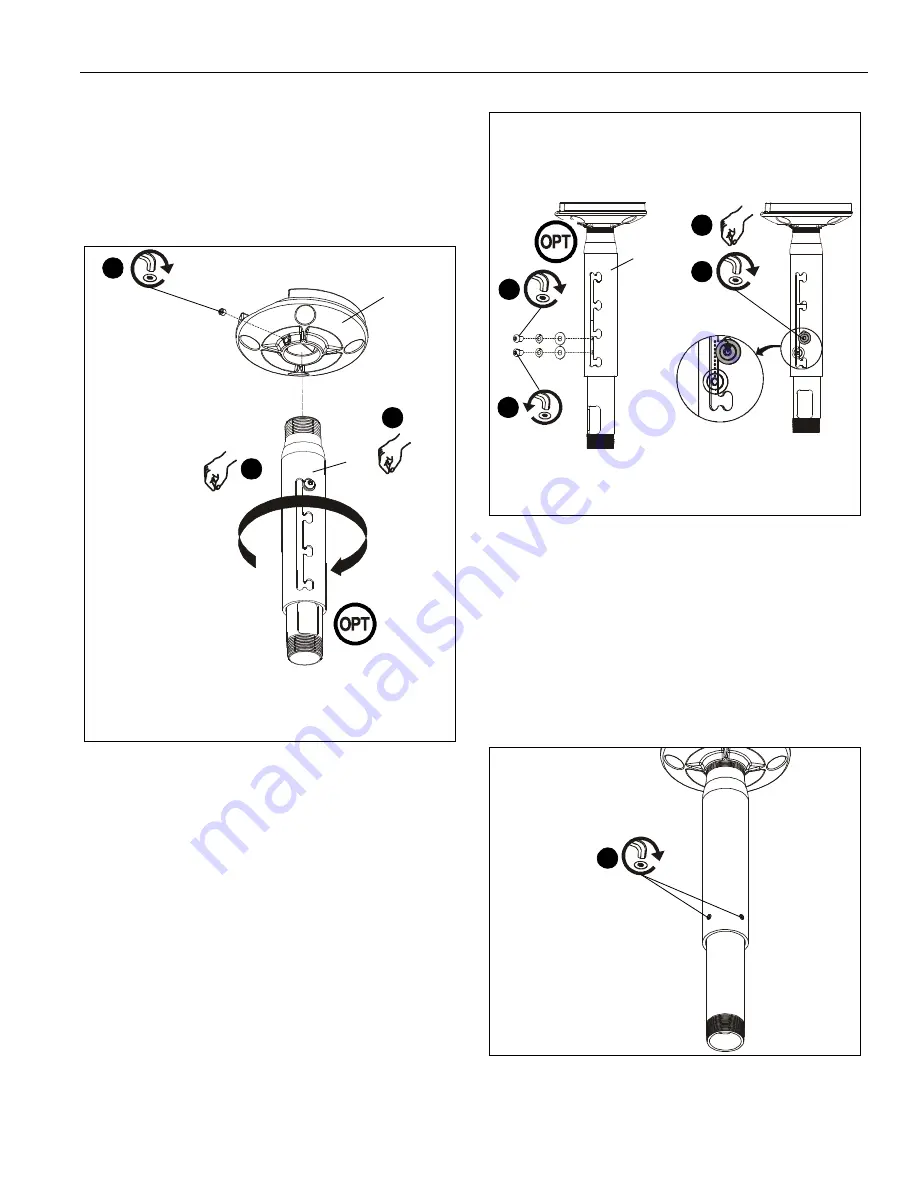
Install adjustable column (A) into plate. (See Figure 4)
Securely tighten column.

Ensure column (A) engages four full threads into plate.

Ensure cable access opening is rotated to desired
position (optional installation, column (A)).

Figure 4

2.

Secure column (A) by tightening set screw (D) in plate using
3/16" hex key (B). (See Figure 4)

NOTE:

Two adjustment holes provided in interior (fixed)

column.  Either adjustment hole can be used to provide
1" (25mm) adjustment increments.

3.

(Optional) Remove button head cap screw and supporting
washers from lower adjustment hole if an additional 1"
(25mm) adjustment increment is desired. (See Figure 5)

4.

(Optional) Replace button head cap screw and supporting
washers into upper adjustment hole to provide an additional
1" (25mm) adjustment increment. (See Figure 5)

Figure 5

5.

Adjust column (A) to desired length, then rotate and lock
into position. (See Figure 5)

NOTE:

Any locking slot can be used to provide 1" (25mm)

adjustment increments.

6.

Tighten adjustment screw using 3/16" hex key (B). (See
Figure 5)

7.

Tighten set screws on back of pipe using 3/16"  key (B).
(See Figure 6)

NOTE:

Optional installation similar; not shown.

Figure 6

4 x

1

1

4 x

(A)

2

(D)

(C)

4

6

5

(A)

3

7

x 2

(rear view)

Summary of Contents for SB-CM32A12

Page 1: ...truções de Instalação Istruzioni di installazione Installatie instructies Instructions d installation All Weather Ceiling Mount Spanish Product Description German Product Description Portuguese Product Description Italian Product Description Dutch Product Description French Product Description SB CM32A12 ...

Page 2: ...horoughly understand and follow all instructions can result in serious personal injury damage to equipment or voiding of factory warranty It is the installer s responsibility to make sure all components are properly assembled and installed using the instructions provided WARNING Failure to provide adequate structural strength for this component can result in serious personal injury or damage to eq...

Page 3: ...PT THREADS 1 1 2 NPT THREADS UP DOWN TILT 15 LEFT RIGHT SWIVEL 75 5 76 146 2 14 00 355 6 MIN 20 00 MAX 508 0 100mm VESA PATTERN VESA PATTERN C L 1 INCREMENTS 4 POSITION SETTINGS 6 00 152 4 2 31 58 6 6 50 165 0 72 6 2 86 39 1 1 54 91 5 3 60 91 5 3 60 0 41 10 3 ...

Page 4: ...raubendreher Chave de fendas Phillips Cacciavite a stella Kruiskopschroevendraaier Tournevis à pointe cruciforme Open Ended Wrench Llave de boca Gabelschlüssel Chave de bocas Chiave a punte aperte Steeksleutel Clé à fourche Pencil Mark Marcar con lápiz Stiftmarkierung Marcar com lápis Segno a matita Potloodmerkteken Marquage au crayon Drill Hole Perforar Bohrloch Fazer furo Praticare un foro Gat b...

Page 5: ...Installation Instructions SB CM32A12 5 PARTS F 1 head assembly G 2 5 16 18 x 3 8 B 1 3 16 A 1 C 1 ceiling plate D 1 5 16 x 1 4 E 4 3 8 adjustable column H 1 5 32 ...

Page 6: ...s See Figure 1 Ensure the following Use OPPOSITE holes in plate C and Marks are in the center of wood joist NOTE Drywall not shown for clarity Figure 1 2 Drill 1 4 diameter pilot holes into wood joist See Figure 2 Ensure pilot holes are straight Figure 2 3 Using 9 16 socket wrench loosely install two minimum Grade 2 not included 3 8 x 2 1 2 lag screws through 3 8 washers E ceiling plate C into woo...

Page 7: ...crements 3 Optional Remove button head cap screw and supporting washers from lower adjustment hole if an additional 1 25mm adjustment increment is desired See Figure 5 4 Optional Replace button head cap screw and supporting washers into upper adjustment hole to provide an additional 1 25mm adjustment increment See Figure 5 Figure 5 5 Adjust column A to desired length then rotate and lock into posi...

Page 8: ... DAMAGE PARTS AND LEAD TO SERIOUS PERSONAL INJURY AND DAMAGE TO EQUIPMENT DO NOT over tighten screws when installing interface bracket WARNING IMPROPER INSTALLATION CAN LEAD TO DISPLAY FALLING CAUSING SERIOUS PERSONAL INJURY OR DAMAGE TO EQUIPMENT Using screws of improper size may damage your display Proper screws will easily and completely thread into display mounting holes Ensure that screws are...

Page 9: ... Adjustments To adjust display Roll Pitch and YAW tension 1 Disconnect all wires and cable from the display 2 Remove two Lower screws securing display to Centris cup 3 Loosen two Upper screws securing display 4 Lift display upward and away from mount 5 Using a hex head wrench turn the tension adjustment screw clockwise to increase tension or counter clockwise to decrease tension See Figure 12 6 Re...

Page 10: ...SB CM32A12 Installation Instructions 10 ...

Page 11: ...Installation Instructions SB CM32A12 11 ...

Page 12: ...SB CM32A12 Installation Instructions 8800 002310 Rev00 12 12 SunBriteTV LLC 2001 Anchor Court Thousand Oaks CA 91320 866 357 8688 www sunbritetv com ...

Reviews: