background image

SunBriteTV Model 3230HD Operator’s Manual

Page 17

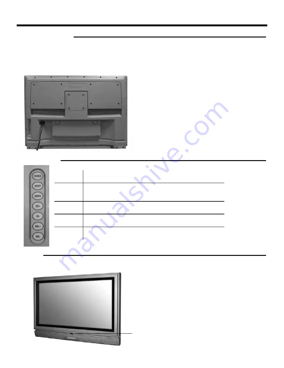
TV Installation - Connecting the Power Cord

Power

Turn on the TV by pressing the button once. Press the button again to 
turn off  the TV.

Input

This button switches between the diff erent sources of the TV. When the 
On-Screen Display (OSD) is active, this button acts as the enter button 
and confi rms the menu selection.

Menu

This button activates the OSD. If a sub-menu is active, pressing this 
button will return selection to the previous menu level.

CH+/CH-

These buttons change the TV channel up or down. If the OSD is active, 
these buttons function as up or down controls for the menu.

Vol+ /Vol-

These buttons increase or decrease the volume. If a sub-menu is active, 
pressing these buttons will move the selection left or right.

IR Sensor

Connect the power cord to a GFCI-protected AC outlet 
with “in-use” waterproof cover.

Warning: TV must be installed at least 5 feet away from 
standing water, such as (but not limited to) a pool or 
spa.

Connecting the Power Cord

WARNING: 
TV AND GFCI RECPTACLE MUST BE INSTALLED AT LEAST 5 FEET AWAY FROM STANDING WATER , SUCH AS (BUT NOT LIMITED 
TO) A POOL OR SPA.
Connect the power cord after you have made connections to your video equipment. 

Side Panel Controls

Front Panel 

Summary of Contents for SB3230HD

Page 1: ...Operator s Manual Model SB3230HD All Weather Outdoor LCD Television April2010v1 Revision 3230HD 090701 ...

Page 2: ... specifies that the cable ground shall be connected to the grounding system of the building as close to the point of cable entry as practical WARNING To reduce the risk of fire or electric shock do not expose the inside of this apparatus to rain or moisture The inside of this apparatus shall not be exposed to dripping or splashing and no objects filled with liquids such as vases shall be placed on...

Page 3: ... Carrying the television requires at least two people FCC Statement This equipment complies with the limits for a Class B digital device pursuant to part 15 of the FCC Rules These limits are designed to provide reasonable protection against harmful interference in a residential installation This equipment generates uses and can radiate radio frequency energy and if not installed and used in accord...

Page 4: ...o not pressure wash SunBriteTV SunBriteTV will resist water exposure from normal rain sprinklers garden hoses etc however it is not designed to withstand pressure washers high pressure water jets or hurricane type weather Do not service SunBriteTV yourself Removal of the television screen cover may expose you to high voltage or other dangerous risks Refer all servicing to a qualified service profe...

Page 5: ...e TV Remote Control Guide On Screen Display Controls Adjusting On Screen Displays On Screen Display Menu Channel Menu Picture Menu Sound Menu Function Menu Set up Menu Information Banner Closed Caption Aspect Ratio Ratings Trouble Shooting Care of SunBriteTV Specifications VGA Timing Codes Features Information and Instructions Internal Thermostatically Controlled Heater Programming Other Manufactu...

Page 6: ...or s Manual Table Top Stand Choose a Location for the TV Important The TV must be installed at least 5 feet from pool spa or other body of water The TV should be installed so the screen is not facing direct sunlight or can be easily turned away from direct sunlight Ideal placement is in an area where the TV is shaded by trees landscape and or structures or under a patio cover or gazebo If the sun ...

Page 7: ...are two Mounting Niches at the bottom of the TV on each side Figure 1 5 Temporarily remove the Table top Stand Mounting Screws Figure 1 Note Never permanently remove the Mounting Screws or any screws from the TV 6 The Table top Stand has adjacent Mounting Holes and a set of two Mounting Catches Figure 2 7 Align the Table top Stand Mounting Holes with the TV Mounting Holes and align the Table top S...

Page 8: ...pull the cover towards you 2 Route the cables to the proper inputs and place the cable cords over the Rubber Sealing Gasket Figure 2 3 Close the cover 4 Press firmly on the cover and screw the Thumb Screws tightly Figure3 Figure 1 Figure 2 Figure 3 Rubber Sealing Gasket Thumb Screws TV Installation Connecting the Power Cord Do not connect power cord until all cable connections have been made Conne...

Page 9: ...t channel audio and red for right channel audio 6 VGA INPUT D SUB This connection port connects to a PC for video using VGA cable Be sure to connect your audio cable to the VGA Stereo input if you want sound out of VGA video source 7 VGA STEREO INPUT This connection port is for people who want to provide audio to the TV when using a PC or a DVI video device The sources use 3 5mm mini jack audio ca...

Page 10: ...Page 10 TV Installation Rear Panel Connections Red Green Blue Yellow Green Red White ...

Page 11: ...f the TV 5 Use the On Screen Display to scan for channels Connecting to Digital Cable without Cable Box or Antenna Connecting to Cable or Antenna 1 Make sure the power of the TV is turned off 2 Connect the Coaxial RF cable from your antenna or cable to the ATSC NTSC port off the back of the TV 3 Turn on the TV 4 Select TV Air for antenna or TV Cable for cable from either your remote control s sour...

Page 12: ...f the TV 3 Turn on the TV and your DVD player 4 Use the remote control s source button or the source button on the TV to switch to HDMI Please Note Refer to the DVD player s manual to make sure the DVD player is configured to output correctly to the TV 1 Make sure the power of TV and your DVD player is turned off 2 Obtain a Component Cable Connect the green color connector to both your DVD player ...

Page 13: ...ECT BOTH 2 Please reference the DVD player s manual as well to make sure the DVD player is configured to output correctly to the TV 1 Make sure the power of the TV and your DVD player is turned off 2 Obtain a Yellow Video Cable Connect the Yellow Video connector to both your DVD player and Composite s Yellow Video connector port off the back of the TV 3 Obtain a RCA Audio Cable Connect the white c...

Page 14: ...port off the back of the TV 4 Connect the red color connector to both your set top box and Component 1 s red connector port off the back of the TV 5 Obtain a RCA Audio Cable Connect the white color connector to both your set top box and Component 1 s white connector port off the back of the TV to the right side of your green blue red component connection 6 Connect the red color connector to both y...

Page 15: ... NOT CONNECT BOTH 2 Reference the set top box manual as well to make sure the set top box is configured to output correctly to the TV 1 Make sure the power of the TV and your set top box is turned off 2 Obtain a Yellow Video Cable Connect the Yellow Video connector to both your set top box and Composite s Yellow Video connector port off the back of the TV 3 Obtain a RCA Audio Cable Connect the whi...

Page 16: ...TING TO AN EXTERNAL SURROUND SOUND RECEIVER 1 Make sure the power of theTV and your receiver is turned off 2 Obtain a Coaxial SPDIF cable connect it to your receiver s coaxial SPDIF digital input and the Coaxial SPDIF connection on the LINE OUT port off the back of the TV 3 Turn on the TV and your receiver Please Note 1 If you want pure digital stream for your receiver to decode you must also conf...

Page 17: ...e the TV channel up or down If the OSD is active these buttons function as up or down controls for the menu Vol Vol These buttons increase or decrease the volume If a sub menu is active pressing these buttons will move the selection left or right IR Sensor Connect the power cord to a GFCI protected AC outlet with in use waterproof cover Warning TV must be installed at least 5 feet away from standi...

Page 18: ...Page 18 TV Installation Starting the TV ...

Page 19: ...ts and moves the item on screen also functions as channel up and down also functions as volume up and down acts as the Enter button for OSD menu and changing channels in conjunction with number buttons MENU Opens Exits the TV menu EXIT Exits the TV menu SLEEP Sets the Sleep timer ASPECT Selects different screen size ADD Adds the current channel FREEZE Freezes the TV picture CC Cycles between diffe...

Page 20: ...Page 20 On Screen Display Controls ...

Page 21: ...ure settings for each port controlling tint contrast sharpness and dynamic noise reduction SOUND The Sound Option changes sound settings for each port controlling digital audio out treble base etc FUNCTION Function Option works only with the Composite and ATSC NTSC port Some of the functions are closed captioning and parental control SET UP The Set up Option works with each port to control Power O...

Page 22: ...Page 22 Adjusting On Screen Displays Channel Menu ...

Page 23: ...SunBriteTV Model 3230HD Operator s Manual Page 23 Adjusting On Screen Displays Picture Menu Picture Menu ...

Page 24: ...Page 24 Adjusting On Screen Displays Picture Menu ...

Page 25: ...SunBriteTV Model 3230HD Operator s Manual Page 25 Adjusting On Screen Displays Picture Menu Sound Menu ...

Page 26: ...Page 26 Adjusting On Screen Displays Sound Menu ...

Page 27: ...SunBriteTV Model 3230HD Operator s Manual Page 27 Adjusting On Screen Displays Sound Menu Function Menu P ...

Page 28: ...Page 28 Adjusting On Screen Displays Function Menu ...

Page 29: ...SunBriteTV Model 3230HD Operator s Manual Page 29 Adjusting On Screen Displays Function Menu Page ...

Page 30: ...Page 30 Adjusting On Screen Displays Function Menu Set Up Menu ...

Page 31: ...SunBriteTV Model 3230HD Operator s Manual Page 31 Adjusting On Screen Displays Set Up Menu ...

Page 32: ...Page 32 Adjusting On Screen Displays Set up Menu ...

Page 33: ...SunBriteTV Model 3230HD Operator s Manual Page 33 Information Banner Information Banner Preset Modes ...

Page 34: ...Page 34 Closed Caption Aspect Ratio ...

Page 35: ...SunBriteTV Model 3230HD Operator s Manual Page 35 Ratings Ratings ...

Page 36: ...Page 36 Trouble Shooting The following table contains the common problems and the solutions to htese problems Please check this list before you contact the technicians ...

Page 37: ...ke Vent Figure 4 Fiber Filter Figure 2 Figure 4 Figure 3 Care of SunBriteTV Figure 1 Intake Vent Fiber Filter Important Information About the Anti Reflective Window on your SunBriteTV Outdoor Television The anti reflective window on your all weather TV is designed to dramatically reduce reflection and improve the contrast of the image on your TV In order to preserve the anti reflective properties ...

Page 38: ...s Stereo Audio Audio Out SPDIF Audio Analog Headphone Jack Speakers Built in water resistant 8 watt x 2 channels Exterior Outdoor rated ASA plastic resin Input Power 100 240VAC 50 60Hz2 5AMax OperatingTemp Non op Temp power applied The non operating temperature feature requires power to be applied AccessoriesIncluded Water resistantremotecontrolwithlithiumbattery Removable table top stand TV Dimen...

Page 39: ...screens are manufactured with rigorous standards to maintain optimal viewing However the LCD screen may have minor defects that appear as a small bright or dark pixel This is common to all LCD screens used in display and television c to SunBriteTV Bright dots are dots that appear bright and unchanged in size when a LCD TV screen displays a black pattern Dark dots are dots that appear dark and unch...

Page 40: ...Page 40 www sunbritetv com u ...

Reviews: