background image

Page 11

880 SERIES

4.3 

Location for the Optional SunSmart™ 2.0 System

IMPORTANT!

 Choose an installation site with the front control panel 

side pointing towards your home’s Wi-Fi router.

CAUTION:

 You must make sure that the spa control panel side 

has a clear unobstructed line-of-site of the home Wi-Fi router. This 

action ensures maximum signal strength between the spa and your 

home’s Wi-Fi router.

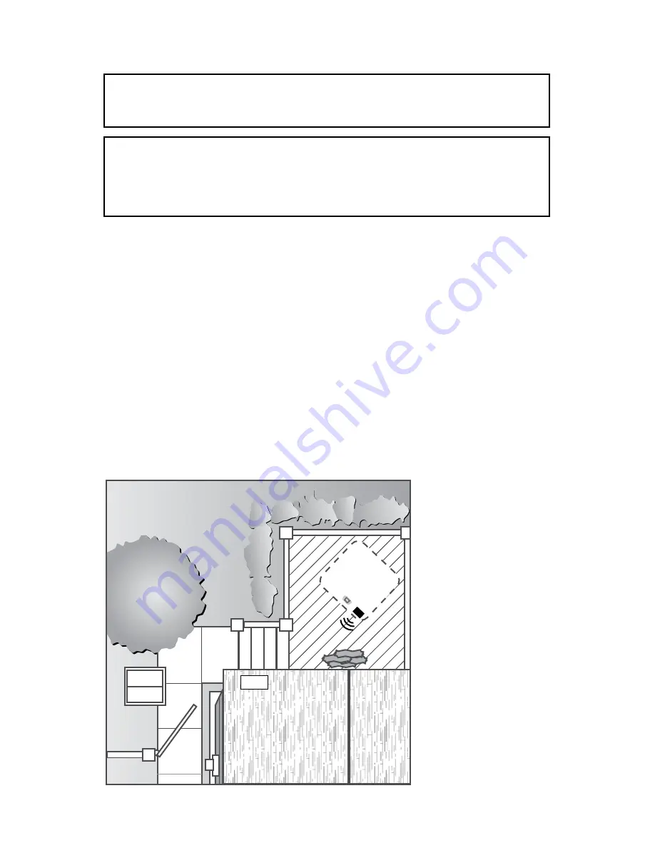
Verify your home router’s Wi-Fi strength at the proposed spa location. 

Front control panel side of spa must point towards your home’s Wi-Fi 

router in your home as illustrated, Figure 4.3a. Stand near the proposed 

front control panel side of the spa with your cell phone, then login to the 

internet using your home Wi-Fi router signal (not 3G or 4G) and verify 

results as follows:

If the home Wi-Fi router signal is strong (3-4 bars) and Internet access is 

stable, the proposed installation site is a good choice.

If the home router’s Wi-Fi signal is weak and Internet access is slow or 

produces an error, the proposed installation site is not a good choice.

•  It may be necessary to choose another spa installation site.

•  Relocate your home Wi-Fi router closer to the spa.

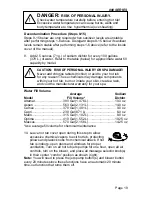
•  Install a “repeater” device in the room closest to the spa to boost the 

home’s router Wi-Fi signal at the proposed spa installation site.

Home WiFi

Router

102

°

Figure 4.3a

Summary of Contents for ALTAMAR

Page 1: ...880 SERIES OWNER S MANUAL Maxxus Aspen Optima Cameo Altamar Marin Capri P N 6530 395C Rev B...

Page 2: ...replacement to properly sanitize your water TO DECREASE RISK OF INFECTION OR DISEASE Always maintain your spa filter as outlined below to ensure healthy spa water Refer to pages 66 68 for additional i...

Page 3: ...b Features 22 9 2 Maxxus Massage Waterfall Selector Diagram 23 9 3 Maxxus Air Controls Diagram 24 9 4 Aspen Hot Tub Features 25 9 5 Aspen Massage Waterfall Selector Diagram 26 9 6 Aspen Air Controls D...

Page 4: ...2 0 Programming and Operation Instructions 54 12 1 Programming the Heating Mode 55 12 2 Programming the Primary Filter 56 12 3 Programming the Secondary Filter 57 12 4 Cleanup Cycle 58 12 5 Blow Out C...

Page 5: ...Handrail Maintenance 78 15 0 Troubleshooting Display Messages 79 16 0 Troubleshooting Procedures 82 17 0 Typical Hot Tub Wiring Diagrams A B North American 60 Hz Models Only 84 18 0 North American 60...

Page 6: ......

Page 7: ...the specifications illustrations and or instructions contained herein 2 0 FCC Notice This equipment has been tested and found to comply with the limits for a Class B Digital Device pursuant to Part 1...

Page 8: ...lead to drowning or severe injury Never use the spa unless all suction guards filter filter lid or skimmer assembly are installed to prevent body and or hair entrapment Never operate or use the spa if...

Page 9: ...GFCI as required by NEC Article 680 42 4 WARNING RISK OF SEVERE INJURY OR DEATH Extreme caution must be exercised to prevent diving or jumping into the spa or slipping and falling which could result...

Page 10: ...spa use may lead to unconsciousness with the possibility of drowning 7 WARNING RISK OF SEVERE INJURY OR DEATH Prolonged immersion in a spa may be injurious to your health Observe a reasonable time li...

Page 11: ...given supervision or instruction concerning use of the appliance by a person responsible for their safety 12 NOTE This spa is not intended nor designed to be used in a commercial or public application...

Page 12: ...or skimmer assembly This has been reported in persons who when submerge themselves underwater allowing hair to come close and or within the reach of the suction fittings suction covers or skimmer ass...

Page 13: ...skimmer assembly Never allow children to play or get near the suction fittings suction covers filter filter lid or skimmer assembly 3 2 Hyperthermia Prolonged immersion in hot water may induce hyperth...

Page 14: ...uch as rails ladders drains or other similar hardware within 10 feet 3m of the spa shall be bonded to the equipment grounding buss with copper conductors not smaller than No 6 AWG 10 mm 5 SAVE THESE I...

Page 15: ...ideration the following The proximity to changing area and shelter especially in regions subject to cold weather The pathway to and from your hot tub this should be free of debris so that dirt and lea...

Page 16: ...ts on has adequate drainage and can handle draining of the entire contents of the spa Be sure to make provisions for ceilings or any other structures that may be below the spas installation Areas arou...

Page 17: ...lustrated Figure 4 3a Stand near the proposed front control panel side of the spa with your cell phone then login to the internet using your home Wi Fi router signal not 3G or 4G and verify results as...

Page 18: ...nt Sundance hot tubs are equipped with a current collector system A pressure wire connector is provided on the surface of the control box located inside the equipment door Figure C page 15 to permit c...

Page 19: ...ire size required refer to Section 7 0 page 16 for your specific hot tub model Wire size must be appropriate per NEC and or local country codes We recommend type THHN wire All wiring must be copper to...

Page 20: ...LY All wires must be hooked up securely or damage could result 10 Install control box door and reinstall the cabinet panel s Figure A Maxxus Aspen Equipment Area 102 8 9 10 6 2 2 13 12 7 4 11 16 3 14...

Page 21: ...3 J52 J4 J61 J62 J49 K11 K10 J59 J44 J48 J39 2A 250VAC F5 30A F4 J28 J30 J27 J34 J29 J50 J56 J57 J63 J37 K8 K4 K6 K7 1 4AT 250VAC F2 J16 J17 J18 ON J1 J6 J9 J20 J21 J19 J67 J12 K3 J11 J13 J14 J15 J10...

Page 22: ...h American 60 Hz Voltage 240 VAC 240 VAC 240 VAC Max Current Draw 1 Pump System 2 Pump System 3 Pump System 28A 28A N A 39A 39A 39A N A 48A 48A Frequency 60 Hz 60 Hz 60 Hz Number of Wires 3 3 3 Circui...

Page 23: ...n be corrosive to metal components WARNING TO DECREASE RISK OF INFECTION OR DISEASE Fill hot tub with clean tap water from garden hose to reduce risk of contracting a waterborne illness e g an infecti...

Page 24: ...er Press either the COOLER Down or WARMER Up button once to display the set temperature for 5 seconds If you want the water to heat to a different temperature simply press COOLER or WARMER within 5 se...

Page 25: ...within your hot tub burn or irritate your skin create a rash and void the manufacturer warranty for your spa Water Fill Volume Average Sodium Model Fill Volume Dichlor Altamar 390 Gal 1 476 L 10 0 oz...

Page 26: ...ed water Water that is too soft can be corrosive to metal components 13 Consult your authorized Sundance Spas dealer for chemical recom mendations then add chemicals to hot tub water to achieve a con...

Page 27: ...d on the inside cover of this manual If sanitizer levels are not stable at this time it will be necessary to repeat this procedure in its entirety steps 1 15 until stable sanitizer readings are achiev...

Page 28: ...Massage Selectors 2 ea 11 Air Injectors 6 ea 12 Suction Covers 6 ea one is not shown 13 Accu Pressure Jets 14 ea 14 Weir Gate Skimmer 15 Filter Lid The filter cartridge and suction fitting filter are...

Page 29: ...assage Selectors 1 2 Massage Selector 1 controls pump 2 Massage Selector 2 controls pump 3 Waterfall Selector 3 Waterfall Selector 3 controls circulation pump output to waterfall Continuously Powered...

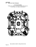
Page 30: ...Diagram Air Control Operation Rotate Air Controls 1 8 to add air to designated jet groups Turn the Blower on to add air to jets group 9 102 2 3 1 5 6 7 4 8 1 1 1 1 2 4 3 4 2 2 4 4 5 6 6 6 6 7 8 9 Spa...

Page 31: ...n fitting filter requires periodic cleaning for opti mum performance 16 Waterfall Control Valve 17 Waterfall Filtration Return 18 Fluidix ST Jets 12 ea 19 Waterfalls 2 ea 20 Pulsator Jets 4 ea 21 Opti...

Page 32: ...assage Selectors 1 2 Massage Selector 1 controls pump 1 Massage Selector 2 controls pump 2 Waterfall Selector 3 Waterfall Selector 3 controls circulation pump output to waterfall Continuously Powered...

Page 33: ...9 6 Aspen Air Controls Diagram Air Control Operation Rotate Air Controls 1 8 to add air to designated jet groups 6 2 1 3 4 5 7 8 1 1 1 2 4 3 3 3 3 6 5 5 5 5 5 5 5 7 8 8 102 Spa operation subject to ch...

Page 34: ...sage Selectors 2 ea 11 Air Injectors 14 ea 12 Suction Covers 4 ea one is not shown 13 Accu Pressure Jets 12 ea 14 Weir Gate Skimmer 15 Filter Lid The filter cartridge and suction fitting filter are lo...

Page 35: ...2 Massage Selector 1 controls pump 1 Massage Selector 2 controls pump 2 Waterfall Selector 3 Waterfall Selector 3 controls circulation pump output to waterfall Continuously Powered Jets 4 5 Jets 4 ar...

Page 36: ...80 SERIES 9 9 Optima Air Controls Diagram Air Control Operation Rotate Air Controls 1 5 to add air to designated jet groups 102 2 3 1 4 5 4 3 3 3 3 4 1 1 1 5 5 2 Spa operation subject to change withou...

Page 37: ...ors 6 ea 12 Suction Covers 4 ea one is not shown 13 Accu Pressure Jets 6 ea 14 Weir Gate Skimmer 15 Filter Lid The filter cartridge and suction fitting filter are located under the filter lid The suct...

Page 38: ...t water between designated jet groups Massage Selectors 1 2 Massage Selector 1 controls pump 2 Massage Selector 2 controls pump 1 Waterfall Selector 3 Waterfall Selector 3 controls circulation pump ou...

Page 39: ...ols Diagram Air Control Operation Rotate Air Controls 1 5 to add air to designated jet groups Turn the Blower on to add air to jets group 6 2 1 3 4 1 5 5 2 2 2 2 1 3 3 3 3 3 6 3 3 3 3 4 5 102 Spa oper...

Page 40: ...s 8 ea 12 Suction Covers 4 ea one is not shown 13 Pulsator Jets 2 ea 14 Weir Gate Skimmer 15 Filter Lid The filter cartridge and suction fitting filter are located under the filter lid The suction fit...

Page 41: ...er between designated jet groups Massage Selectors 1 Massage Selector 1 controls pump 2 Waterfall Selector 2 Waterfall Selector 2 controls circulation pump output to waterfall Continuously Powered Jet...

Page 42: ...Air Controls Diagram Air Control Operation Rotate Air Controls 1 5 to add air to designated jet groups Turn the Blower on to add air to jets group 6 102 3 3 1 1 1 1 6 4 5 2 2 3 2 4 5 1 Spa operation s...

Page 43: ...g filter are located under the filter lid The suction fitting filter re quires periodic cleaning for optimum performance 16 Waterfall Control Valve 17 Waterfall Filtration Return 18 Fluidix ST Jets 10...

Page 44: ...etween designated jet groups Massage Selectors 1 Massage Selector 1 controls pump 2 Waterfall Selector 2 Waterfall Selector 2 controls circulation pump output to waterfall Continuously Powered Jets 3...

Page 45: ...Air Controls Diagram Air Control Operation Rotate Air Controls 1 4 to add air to designated jet groups Turn the Blower on to add air to jets group 5 102 2 2 1 3 1 1 1 5 2 2 4 3 1 4 Spa operation subj...

Page 46: ...jectors 10 ea 12 Fluidix Reflex Jets 6 ea 13 Pulsator Jets 2 ea 14 Fluidix Intelli Jets 2 ea 15 Vortex Jet 1 ea 16 Filter Lid The filter cartridge and suction fitting filter are located under the filt...

Page 47: ...tate Massage Selector 1 to divert water between designated jet groups Massage Selectors 1 Massage Selector 1 controls pump 1 Waterfall Selector 2 Waterfall Selector 2 controls circulation pump output...

Page 48: ...Capri Air Controls Diagram Air Control Operation Rotate Air Controls 1 2 to add air to designated jet groups Turn the Blower on to add air to jets group 3 102 2 1 3 2 2 1 1 1 1 Spa operation subject t...

Page 49: ...skipped you will be able to activate components but after 10 minutes the screen will revert back to the registration screen This process will continue until the spa is registered and the passcode is...

Page 50: ...ster your spa online you can then enter the registration information into the control panel Note If a number is entered wrong you can tap to move backwards 1 From the registration screen Figure 10 2a...

Page 51: ...temperature of the spa Increase the temperature by tapping in 1 increments Decrease the temperature by tapping in 1 increments Note The temperature range for the spa is 65 to 104 F 18 33 to 40 C To ac...

Page 52: ...s NOT automatically adjust for daylight saving time The time must be manually adjusted 11 0 Operating Instructions Your Sundance Spas hot tub has a touch sensitive control panel massage selector valve...

Page 53: ...jet operation you may simply turn the pump s back on B Air Injection Tap to turn the blower on and off The air blower forces air through the injectors and Focus Relief Jets The blower automatically t...

Page 54: ...nd 1 20 0 0 Tap to lower the intensity of the lights to the minimum level of 0 Speed Control Button Increase Controls the blending speed for the lights Tap to increase the blending speed of the colors...

Page 55: ...The display will change to Figure 11 3b Once you enter the Music Menu tap the power button to turn the stereo on Your connected electronic device Bluetooth or auxil iary provides the audio entertainm...

Page 56: ...low the steps below Note The BT icon cannot be selected manually unless a Bluetooth connection is established with your device If you experience a connec tion problem with your Bluetooth device make s...

Page 57: ...bass setting to create a custom sound Bass Treble Adjustment Bars Tap or to adjust the Bass Treble range from 5 to 5 This feature can be used to create a custom sound Rock Preset Tap to activate the R...

Page 58: ...elief The jets in your new hot tub offer the advantage of no moving parts and zero maintenance They can also be adjust ed for a high and low impact massage providing the ultimate massage To adjust jet...

Page 59: ...hot tub water by the air coming through the injector system when the air blower is on WARNING TO DECREASE RISK OF PERSONAL IN JURY Always turn off the air blower before removing or installing SunScen...

Page 60: ...d filtration programming page 55 Water Care Water Care Provides access to the water care programming page 58 Wi Fi Wi Fi Provides access to the Wi Fi settings page 61 Lock Lock Provides access to acti...

Page 61: ...ter the menu Then select one of the heating settings A Auto heating 1 When programmed to Auto the spa will maintain the water temperature to the set temperature Heating will occur when necessary 2 To...

Page 62: ...but the circulation pump comes on for 2 hours to heat the water after the cycle has finished The next primary filter cycle will only be for 6 hours not 8 hours A To change the default cycle When you...

Page 63: ...gure 12 3a to enter the Secondary Filter programming Figure 12 3b During a secondary filtration the Jets Pump 1 is activated There are 3 cycles you can select from Figure 12 3b The factory default cyc...

Page 64: ...cycle will purge the air from the plumbing lines normally caused by draining and filling the spa The Jets Pump 1 and the Circulation Pump will turn on for 1 minute and then shut off Then Jets Pump 2 w...

Page 65: ...panel display Figure 12 6d The CLEARRAY UV bulb must be replaced page 75 and the timer must be reset Tap reset and follow the instructions above to reset the timer If you tap snooze the message will c...

Page 66: ...your changes 4 When the timer expires a message will appear on the control panel display Figure 12 6h The filter must be cleaned or replaced Follow the instructions above to reset the timer If you tap...

Page 67: ...up 1 You need to follow the instructions from the App in order to connect the Wi Fi 2 While the system attempts to connect you will see the Spa Wi Fi Setup in progress Figure 12 7b When the connection...

Page 68: ...9 Then move on to the next number until a four digit code has been selected 3 Tap to activate the locking feature 4 The adjust temperature feature is disabled but the spa will still perform all sched...

Page 69: ...ntering the code Then move on to the next number until the four digit unlock code has been entered 3 Tap to unlock 4 Tap to return to the Setting Menu 12 9 Programming the Time and Date From the Setti...

Page 70: ...enter the language options Figures 12 10a and 12 10b 1 There are 4 languages to select from English French Deutsch and Espa ol To select a language tap the language tab you want to display Figure 12 1...

Page 71: ...ghlight the Information Menu tab Tap Information to enter the selection menu Figures 12 12a and 12 12b There are no selections that can be made The menu simply provides information Figure 12 12b Figur...

Page 72: ...rated less than the flow rate marked on the original suction fitting Using improper suction fittings or suction covers can create a body or hair suction entrapment hazard that may lead to drowning or...

Page 73: ...se off MicroClean Ultra Insert 2 monthly and replace every 6 months or as needed 6473 164 Filter Removal Instructions Loosen filter nut to provide clearance then remove MICROCLEAN Ultra Filter Assembl...

Page 74: ...s 3 Install filter insert 2 into outer pleated filter 1 by gently sliding inward until a slight resistance is felt approximately 1 4 from bottom Lightly tap insert end with palm of hand to snap in pla...

Page 75: ...are certain precautions to keep in mind when draining your hot tub If it is extremely cold and the hot tub is outdoors freez ing could occur in the lines or the equipment see Winter izing page 72 On...

Page 76: ...slice valve by pushing it downward and sliding the handle to the side Remove the adapter and reinstall the Quick drain cap before refilling hot tub 13 4 Cleaning The Hot Tub Interior To preserve the...

Page 77: ...ance Spa Dealer for recommended cover care and conditioning products Condition using non petroleum based conditioners to keep the vinyl supple and threads stitching from drying out Do not use solvents...

Page 78: ...d from the hot tub and equipment to protect against damage from freezing Expert winterization of your spa is highly recommended contact your authorized Sundance Spas dealer In emergency situations dam...

Page 79: ...in certain sections of the piping may still be frozen This situation will block water flow preventing the hot tub from operating properly and possibly damaging the equipment We recommend you consult...

Page 80: ...itizer must be used regularly Your Sundance hot tub is equipped with the Brominator a special compartment built into the floating skimmer gate to hold the SunPurity mineral cartridge designed specific...

Page 81: ...rly working CLEARRAY is standard for all models After a year the bulb must be replaced A message will appear on the LCD display when the time allotted has expired In order to clear the message a new U...

Page 82: ...quartz tube 8 For cleaning the quartz tube follow steps 7 and 8 then proceed from step 9 For replacing quartz tube skip steps 7 and 8 and proceed from step 9 7 Cleaning quartz tube Clean the quartz tu...

Page 83: ...CH THE NEW UV BULB WITH YOUR BARE HAND Oil on your skin will cause hot spot on the UV bulb and shorten the life of your UV bulb Use the provided latex glove to handle the UV bulb 15 Slide the new UV b...

Page 84: ...hways chemical treatments added to swimming pools and hot tubs and ground water in numerous coastal areas The good news is with proper care your hot tub s handrails can maintain their original finish...

Page 85: ...The flow switch is malfunctioning closed Contact your authorized dealer or service organization 3 Shorted Hi limit Temp Sensor The hi limit temperature sensor is not functional Heater is disabled This...

Page 86: ...ing If condition persists contact your authorized dealer or service organization Note The heater icon will be blinking and the error icon will be displayed under the temperature 12 Watchdog Protection...

Page 87: ...ined and refilled with fresh water 22 Extended Temperature Activated The spa is set to go up to 104 F 40 C but it can be set to reach 106 F 41 C To access the extended temperature you need press and h...

Page 88: ...erate and icon does Depress JETS Button 1 If no sound is detected or if a buzzing sound is detected turn off power to the spa and contact your authorized dealer or qualified service technician 2 If mo...

Page 89: ...ges 22 40 1 Make certain the jets pump is turned on 2 Check position of massage selectors 3 Open air control for selected jet system 4 Check for adequate water level 5 Check for dirty filter pages 66...

Page 90: ...3 Wires to Hot Tub 2 Hot L1 L2 1 Ground White N Black L1 Red L2 240 VAC No Load Neutral Wire Note service disconnect not shown in this diagram Red L2 Red L2 Pigtail Neutral Bus Ground Black L1 Black L...

Page 91: ...UMP1 J27 J34 J29 J50 J56 J57 J63 F7 J2 F6 F2 F1 F5 F4 J37 K8 K4 K6 1 4AT 250VAC WATER TEMP SERIAL ADCM FLOW HI LIMIT TEMP J16 J17 J18 ON J1 J9 J11 J13 J14 J15 J10 J24 ZONE 2 J23 ZONE 1 C58 C57 K2 GFCI...

Page 92: ...C57 K2 GFCI TRIP J8 HEATER J3 J38 J53 J45 J46 J47 J41 J58 J42 J31 J32 J33 J40 J64 J36 J35 1 2 3 4 S1 FUSE CIRC OZONE STATUS INDICATOR GRN J7 J69 J68 WI FI OPTIONAL CONTROL PANEL FLOW SENSOR WATER SEN...

Page 93: ...A is the factory default setting for 3 pump models DOMESTIC DIP SWITCH SETTINGS S1 LOCATION 40A 50A 60A 1 2 3 4 5 6 7 8 9 10 OFF OFF ON OFF OFF OFF OFF OFF OFF OFF ON OFF 1 2 3 4 5 6 7 8 9 10 OFF OFF...

Page 94: ......

Page 95: ......

Page 96: ......

Reviews: