Page 42
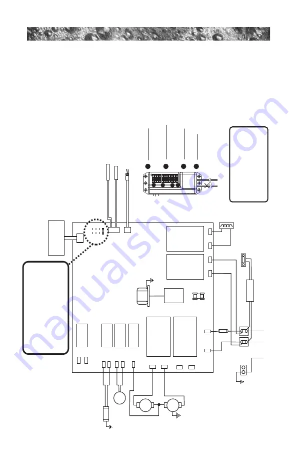
16.0 North American Camden Circuit Diagram
This wiring diagram is used for all North American Camden 240 VAC
(60Hz) dedicated power models
.
Ster
eo
(Optional)
Power Supply
O
zo
n
at
or
(
O
p
ti
on
al
)
O
3
GRN
TB1
Standard 240 V
AC, 3-W
ir
e Connection (60Hz, 1-Phase Ser
vice)
USE COPPER CONDUCTORS ONL
Y. WIRE SIZE MUST
BE APPROPRIA
TE PER NEC AND/OR LOCAL CODES
RED
RED
J6
BLK
J5
WHT
WHT
WHT
RED
BLK
BLK
BLK
RED
RED
BLK
BLK
BLK
2
1
Flow Switch
Hi - Limit/Fr
eeze Sensor
Temperatur
e Sensor
J1
J2
J3
F1
30A, 250V
SC-30
Pu
m
p
1
Tr
an
sf
or
m
er
24
0
va
c
J4
F1
JP1
4
2
3
1
6
5
8
7
7
6
2
4
HI
LO
C
C
on
tr
ol
P
an
el
Cir
c.
Pump
J20
K1
K2
K3
K4
K5
K6
K7
K8
J21
J11
J12
J13
J14
J15
J16
J17
J18
J19
J7
J8
J9
J10
Logic Jumper Settings (Factor
y Defaults Shown)
JP1
1-2
ON
=
40A Logic
JP1
1-2
OFF
=
50A Logic (Factor
y Default Setting
JP1
3-4
ON
=
2 Pump Operation
JP1
3-4
OFF
=
1 Pump Operation
JP1
5-6
ON
=
Not Used
JP1
5-6
OFF
=
Not Used
JP1
7-8
ON
=
ºC T
emperatur
e Display
JP1
7-8
OFF
=
ºF T
emperatur
e Display
This device complies with Part 15 of the
FCC rules. Operation is subject to the
following two conditions:
1.
This device may not cause harmful
interfer
ence.
2.
This device must accept any intefer
ence
received including interfer
ence that may
cause undesir
ed operation.
Heater 5.5 kW 240 V
AC
Photocell I/P Temperatur
e
Pr
obe
Blue wir
es 12 V
AC
constant voltage (connects to the yellow wir
es on
the
transformer)
Gray W
ir
es
(Not Used
)
Light DCU
Not Used
Zone 1 (Blue T
ape)
Exterior Lighting
and Accessories
Zone 2 (Gr
een T
ape)
W
aterfall, Air contr
ols
and Diverter
Zone 3 (Red T
ape)
Footwell
Aux Connector
Contr
ol Panel
A
B
C
D
A
B
C
D
Summary of Contents for CAMDEN 780
Page 1: ...7 8 0 o w n e r s m a n u a l Camden Certa Chelsee Dover Hamilton 6530 436T Rev B ...
Page 62: ...Page 58 Notes ...
Page 63: ...Page 59 Notes ...
Page 64: ......


