insulation shall have a maximum operating tempera-
ture of 220
°
F or higher. The wall thickness of the pipe
insulation should be not less than
1
/
2
”. A 1” wall thick-
ness is required for exposed piping in all areas prone to
annual hard freeze conditions. When it comes to pipe
insulation the rule is simple: thicker is better.
To the extent possible, slide the insulation material
over the pipe without cutting or taping. All butt joints
must be sealed with contact adhesive. The use of rigid
polyethylene pipe insulation is prohibited. The temper-
atures generated by your collector in the summer
months or under stagnation conditions can melt this
type of material.
Any above ground exterior pipe insulation is subject to
UV degradation and must be jacketed, wrapped with
aluminum foil tape, or painted with two coats of high
quality water-based acrylic resin coating as supplied by
the insulation manufacturer.
4.6 Control System
4.6.1 Differential Controller
The differential controller must be installed in an acces-
sible location so that the user interface, typically an
LCD screen, can be seen. Switches on the controller
must be labeled and accessible. Always follow the con-
troller manufacturers wiring instructions when installing
differential controllers. Control system inputs; such as
signals from the temperature sensors or flow meters
shall be connected to the appropriate low voltage ter-
minals. Controller output to the pumps will be medium
voltage, 110 VAC or 220 VAC. Medium voltage power
to the pump may be supplied by a line cord from the
pump to an outlet in the controller or hard wired from
the controller medium voltage terminals to the pump.
Wiring must comply with standard electrical practice
and all applicable electrical codes for the jurisdiction
having authority, this may require the use of conduit
for medium voltage wiring.
The differential controller must have a provision to
manually turn the pump on and off (manual override)
so that the pump operation can be checked at any time
and the pump can be manually stopped if required for
maintenance or troubleshooting purposes.
Set the maximum tank temperature to the desired
maximum temperature, this temperature must be low-
er than the rated maximum temperature of the tank an
associated components. When the solar loop heats the
tank to the temperature, the pump will shut off
preventing further heat gains to the solar tank.
4.6.2 Collector Sensor Placement
The collector sensor shall be located on the solar loop
return line as close to the collector as possible. Sensors
are typically accurate to
±
1
/
2
°
F if properly installed and
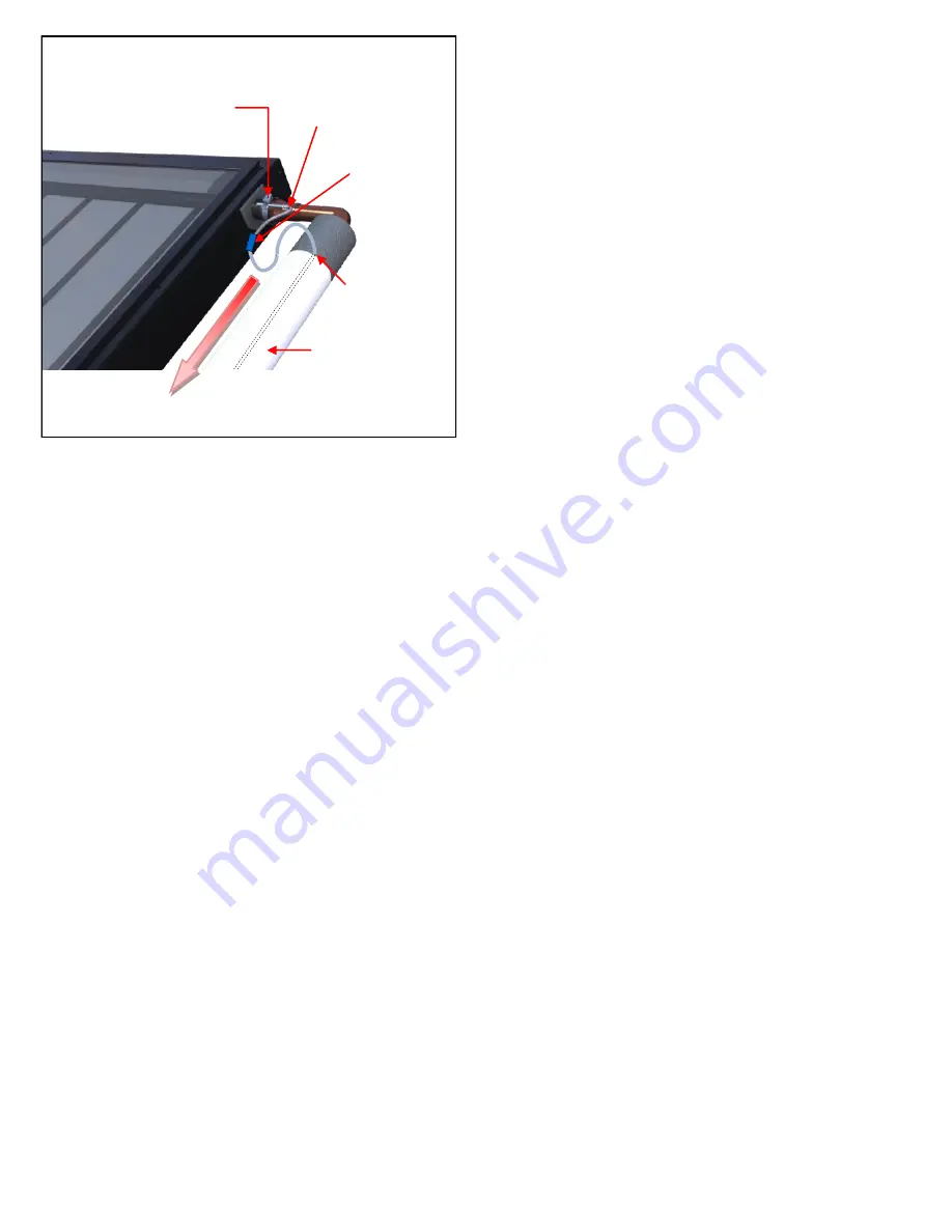
weatherized. The collector probe sensor shall be at-
tached to the SunEarth collector header pipe either
with a stainless steel hose clamp or by inserting the
probe sensor into a thermal well in contact with the
fluid near the outlet header pipe.
It is recommended that the connection between the
silicon sensor lead and low voltage sensor wiring be
made inside the attic, a NEMA 4X junction box or some
other indoor space. When using wire nuts to make the
connection, the crimped brass cap on the end of the
sensor should be removed and the wire stripped before
inserting into the wire nut for connection. Where con-
nections from the sensor lead to the low voltage wiring
is made at an exposed location the connection should
be crimped and insulated with heat shrink or soldered
and insulated with heat shrink. Wire nuts or screw con-
nectors should not be used in exposed locations due to
the likelihood of corrosion which will result in a com-
promised electrical connection. Thoroughly wrap and
weatherize the insulation with electrician’s tape or insu-
lation tape as provided by the manufacturer. See Fig-
ure 12 for collector sensor installation detail.
If an electrical potential exists between the roof and
ground, this may induce current in the collector sensor
wire. This current will result in a false signal being re-
ceived by the controller and hence incorrect tempera-
ture measurements. To prevent this current the collec-
tors absorber plate and piping should be independently
earth grounded. This will provide a separate path to
ground from the roof which does not interfere with the
sensor readings.
Grounding can be achieved by running a separate
ground wire to the collectors or ensuring that the pipe
in the solar loop is grounded and that there are no
electrical discontinuities between the grounding point
and the collectors absorber. Grounding of the collector
& roof piping is especially important in locations that
often experience electrical storms and electrical atmos-
pheric activity.
4.6.3 Low Voltage Wiring
The low voltage wiring used in to connect the sensor
lead to the controller shall be a minimum 18 AWG. The
COLLECTOR SENSOR
Fig.12
SILICON SENSOR LEAD MAY
BE IN CONTACT WITH PIPE
SENSOR CLAMPED TO HEADER PIPE
& COVERED WITH INSULATION
CRIMP OR SOLDER
CONNECTION
SENSOR WIRE
MUST
NOT
BE PLACE IN
DIRECT CONTACT
WITH PIPE
PROTECTIVE INSULATION
JACKET OR APPROVED
COATING
RETURN LINE
Summary of Contents for CASCADE 2
Page 29: ...APPENDIX F ...
Page 30: ...APPENDIX F ...


