wiring should be bare or tinned copper, two conductor,
stranded, PVC insulated, with a PVC UV rated jacket
suitable for exterior use. In locations that often experi-
ence electrical storms and electrical atmospheric activi-
ty the low voltage sensor wire should also be shielded
with the shielding grounded.
Low voltage wire shall be rated for the full ranges of
temperatures expected in the location, typically wire is
rated up to 160
°
F. The low voltage sensor wire must
not be in direct contact with the pipes as the wire insu-
lation may melt when in contact with a hot pipe. Low
voltage sensor wire must be run OUTSIDE the pipe in-
sulation. Where the low voltage wire is run in an ex-
posed location, it should be run OUTSIDE the pipe insu-
lation but UNDER the insulation jacket or wrap to pro-
tect the wire from UV exposure.
4.7 Installing the Solar tank
The solar tank is heated indirectly through the external
heat exchanger by separate pumps on the collector
loop and the potable side of the heat exchanger.
When plumbing the SunEarth solar storage tank and
drainback reservoir make sure that all the components
are accessible and easy to reach. Ensure that there is
clear access to the storage tank, circulating pump,
drainback reservoir, mixing valve, flow meter and other
key components. If a component in the potable water
side of the system may require future service or
maintenance make the connections with brass unions.
Use only brass nipples and unions and copper and
brass fittings in plumbing the solar storage tank and
drainback reservoir. The use of galvanized fittings or
nipples, CPVC or PVC piping is prohibited.
Check valves are NOT ALLOWED anywhere in the col-
lector loop. A check valve in the collector loop will pre-
vent proper draining of the collectors and may result in
freeze damage. If the pump used has an integral
check valve, the check valve must be removed before
installing the pump in the system.
Hard copper connections to the city cold water supply
line and the home hot water feed lines are recom-
mended. The gaskets in standard water heater flex
hose connectors can become brittle and compressed
over time and begin leaking on the water heater. If
not detected in a timely manner even a small drip or
leak may cause serious damage to the tank’s electrical
components or, in extreme cases, may cause the tank
to leak from the outside in.
Tank plumbing is required to provide for the isolation of
the solar storage tank from the city cold water supply
line by means of an isolating ball valve.
The differential temperature controller shall have a
screen readout to show temperatures of the collector
and storage tank. Otherwise, line thermometers shall
be installed in the collector supply and return lines to
allow for a simple diagnostic check of proper system
operation. On a sunny day the hot water return line
should be approximately 5 – 15°F warmer than the wa-
ter in the collector supply line.
The specified SunEarth controller continuously displays
the temperature of the SunEarth collectors (T1) and
the temperature at the bottom of the solar tank (T2).
In addition, you may choose to install a third tempera-
ture sensor (T3); this is normally installed at the hot
water outlet on both single and double tank systems.
The Torrent Drainback system typically requires a high
head, low flow circulating pump. The maximum head
on the pump curve must be greater than the static lift
head required to fill the system. The static lift head is
the vertical height from the bottom of the drainback
tank to the highest point in the system (usually the col-
lector outlet header). When the pump is filling the sys-
tem it will be pumping against the static lift head and
should provide no less than 0.5 GPM flow. Once the
system has been filled to the top of the collector, water
will start to cascade down the return line filling the re-
turn line as far as the drainback reservoir. Once this
pipe is fully flooded the return line will start to siphon,
resulting in an increase in flow as the system transi-
tions from the filling condition to the running condition.
In the running condition the flow rate should not ex-
ceed 5 GPM. Good pump selection requires that the
pump provide enough lift for the filling condition with-
out excessive flow in the running condition. This is
usually achieved using a pump with a “steep” pump
curve. For multistory buildings, this can be especially
challenging unless the drainback tank is located on the
upper floor.
When there is a risk of pump cavitation due to high
flow rates, a pump throttling valve (COMPONENT #22)
may be located on the discharge, or upstream, side of
the pump to adjust the solar loop flow rate and to pre-
vent cavitation of the circulating pump. Cavitation is a
fluid condition that can lead to pitting or other damage
to the pump impeller. A throttling valve on the return
piping from the collector to the drainback tank can also
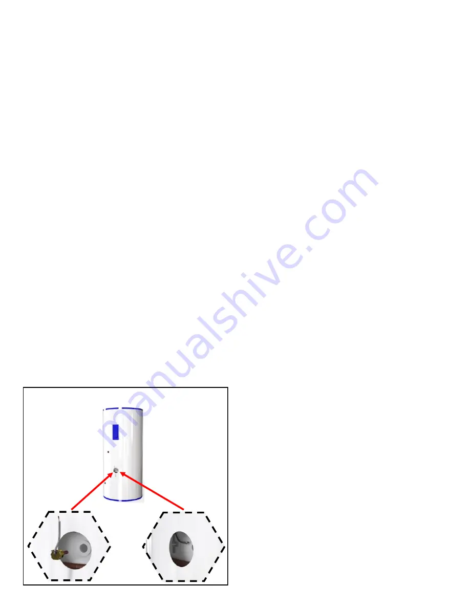
TANK SENSOR
Fig.13
THERMOWELL
JIFFY CLIP (ALTERNATIVE)
Summary of Contents for CASCADE 2
Page 29: ...APPENDIX F ...
Page 30: ...APPENDIX F ...


