the drainback on the uppermost floor, preferably near
the ceiling.
Drainback tanks are factory insulated to provide both
heat retention and a noise buffer against the sound of
falling water.
If your Torrent Drainback system includes the optional
flow meter it should be plumbed so that the top of the
flow meter is level with the top of the drainback tank
so that the flow meter also provides a visual check of
the fluid level in the system. The top and bottom of
the flow meter should be supported to relieve stresses
on the connecting unions.
DO NOT install the pressure relief valve (COMPONENT
#9) on the drainback tank at this time. The COMPO-
NENT #9 is threaded in place after the solar loop piping
has been filled with water. See Section 4.13 for in-
structions on charging the system.
4.12 Electrical and Wiring Requirements
When the electric element is used as the auxiliary heat
source a properly licensed contractor shall make the
230 VAC electrical connection to the water heater or
storage tank. If your solar contractor is not allowed by
law to make these connections consult a licensed elec-
trician.
Never activate the circuit breaker controlling the elec-
trical heating element until the solar storage tank is
completely filled with water. This will prevent “dry fir-
ing” and destruction of the heating element.
SunEarth recommends the use of a 115 VAC differen-
tial control with a factory installed six foot line cord.
The installation requires one 115 VAC outlet to be lo-
cated neat the solar storage tank. The circulation pump
line cord is then plugged into the receptacle on the
controller. A 230 VAC control and circulation pump may
be substituted where appropriate.
4.13 Heat Transfer Fluid (HTF)
The HTF must be a non-toxic fluid that meets FDA Gen-
erally Recognized as safe (GRAS) Classification. The
Torrent Drainback System uses water to meet this re-
quirement.
Water used to fill the collector loop must meet certain
minimum standards for purity. Impurities in the dilu-
tion water can increase metal corrosion, and cause the
formation of scale and other deposits on the heat ex-
changer’s internal heat transfer surfaces. Distilled or
deionized water is recommended.
4.14 Flushing and Filling the System
Once the components have been plumbed it is time to
fill the solar storage and collector loop with water as
follows:
4.14.1 STEP 1 – Flush and Fill the potable loop with
water.
Close
potable
flushing
combination
valves
(COMPONENTS #24 & 36). Fill the solar tank with wa-
ter and check that there are no leaks on the potable
side of the system.
Do this by opening the cold water isolation ball valve to
the solar tank (COMPONENT #8) and opening a hot
water outlet, such as a faucet, until the water runs
freely. When the tank is filled, inspect all threaded fit-
tings and solder joints for leaks.
Connect a washing machine hose to the drain ports of
the potable flushing combination valves (COMPONENT
#24 & 36). Open domestic flushing combination valves
drain ports (COMPONENT #24 & 36).
Open potable flushing valve (COMPONENT #36) and
close valves drain port when water flows out of the
hose. Close domestic flushing valve (COMPONENT #24)
drain valve when water flows clear from the hose.
Open potable flushing valve (COMPONENT #24). Check
for leaks. The entire potable piping is now pressurized
with potable water.
4.14.2 STEP 2 - Flush and Fill the solar loop piping with
water.
Close solar flushing combination valves (COMPONENTS
#11 & 35).
Connect a washing machine hose to the solar flushing
combination valve drain port (COMPONENT #11), open
the solar flushing valve drain port (COMPONENT #11).
Connect the other end of the hose to a water pressur-
ized water source or a utility pressure pump.
Connect a washing machine hose to the solar flushing
combination valve drain port (COMPONENT #35), open
the solar flushing combination valve drain port
(COMPONENT #35). Open the water pressurized water
source. Run until clear water runs from the washing
machine hose connected to the solar flushing combina-
tion valve drain port (COMPONENT #35).
Open the solar flushing combination valves
(COMPONENTS #11 & 35). Close the solar flushing
combination valves drain ports (COMPONENTS #11 &
35), turn off the water source. Verify water level in
drainback tank is within 1 inch from the top of the sight
glass or flow mater; fill or drain as necessary.
4.14.3 STEP 3 – Run the pump to check operation and
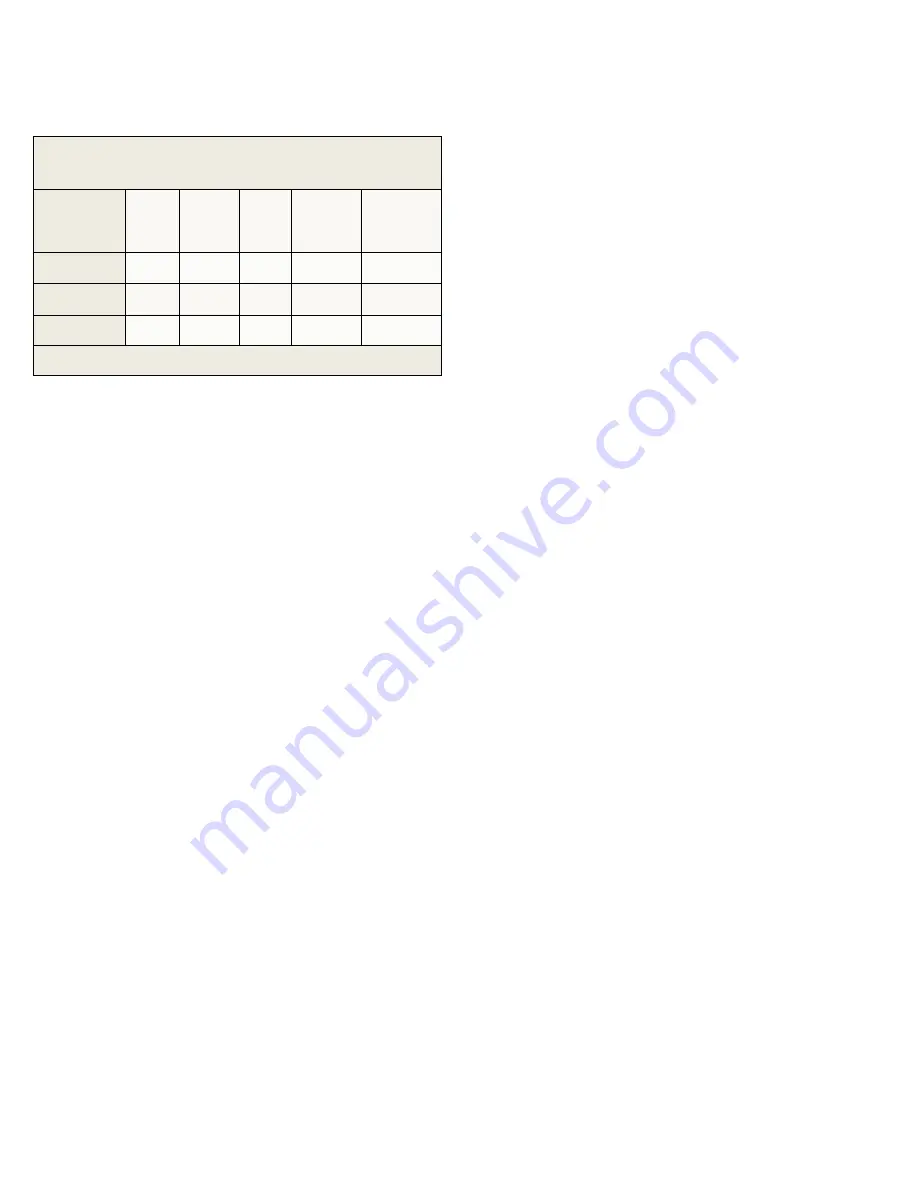
TABLE 3—Specifications for SunEarth CopperStor
Drainback Reservoirs
SUNEARTH
MODEL
NUMBER
WIDTH
(IN)
LENGTH
(IN)
DEPTH
(IN)
DRY
WEIGHT
(LBS)
FLUID
CAPACITY
(GAL)
DB-5
12
50
5
42
5.0
DB-7.5
18
50
5
56
7.5
DB-10
24
50
5
84
10.0
MAXIMUM PRESSURE 160 PSIG, CONNECTIONS 3/4”
Summary of Contents for CASCADE 2
Page 29: ...APPENDIX F ...
Page 30: ...APPENDIX F ...


