background image

P.10

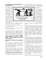
In a single tank system install a third thermome-
ter (No. 3) directly after the mixing valve above the
solar storage tank.  In a two tank system you may
install the third thermometer either directly above
the hot outlet on the solar storage tank or after
the mixing valve on the back-up water heater.

Two way ball valves must be installed on either
side of the circulating pump (Nos. 12 and 14) so
that the pump can be isolated from the collector
loop.  Repairs or routine system maintenance can
be completed without introducing air into the
system or draining the HTF (Nos.12 and 14).

The expansion tank shall have a minimum 150
PSIG working pressure and have a total volume
of not less than 4.4 gallons.  The standard facto-
ry charge should be 40 PSIG.  The expansion tank
shall be Rheem/Ruud Therm-X-Guard Model RRT-
12 or equal (No. 8).

A high quality thermostatic mixing valve is a
required component in all OG-300 certified sys-
tems and should be plumbed in line with brass
union connections for ease of future repair or
replacment (No. 31).  The specified mixing valve
shall be the Heatguard model HGBASE or equal
and shall have an operating range between 95°F
and 140°F.  The mixing valve shall be set to 120°F.

The 3/4" cold water supply line to the solar stor-
age tank must be insulated with minimum 7/8"
X 1/2" pipe insulation to a minimum distance of
5' behind the storage tank, or to the wall if clos-
er than 5'.

The temperatures generated by your SolaRay sys-
tem will vary throughout the year.  In the
Northern Hemisphere the water temperature will
be hottest in the spring and summer months
while cooler temperatures are to be expect from
November through March.  On sunny days sys-
tem temperatures may range between 110ºF to
180ºF depending upon the season and hot water
demand.  The mixing valve described above
blends the hot and cold water supplies to deliver
hot water to your fixtures at a safe, controlled
temperature.

WARNING:  SCALDING CAN OCCUR WITHIN
FIVE SECONDS WHEN WATER TEMPERA-
TURES APPROACH 140ºF.  THE MIXING VALVE
SHOULD BE ADJUSTED BY YOUR CONTRAC-
TOR TO PROVIDE WATER TO YOUR FIXTURES
AT NO MORE THAN 120ºF.

4.9  Tank Insulation

SunEarth requires that the solar storage tank
must have a minimum insulation value of R-20.
Most solar storage tanks now come with R-16.7
factory insulation.   Conventional back-up elec-
tric water heaters have insulation values between
R-12 and R-20.  The R value expresses the ther-
mal conductivity of the insulation material. The
higher the "R"value the more effective the insu-
lation material is at preventing heat loss.

Whereas solar storage tanks do not come with
sufficient factory insulation to meet SunEarth’s
insulation specification, a supplemental insula-
tion jacket also must be installed.  We recom-
mend an aluminum foil "bubble-pack" insulation
material such as manufactured by Reflectix (or
equal).  When properly applied, the insulation
jacket will increase the overall level of the solar
tank insulation to approximately R-22.  In two
tank retrofit installations an installation jacket
also must be installed on the back-up water
heater.  

If your Solaray system is installed in a new home,
SunEarth specifies that the conventional water
heater in a two tank system have an insulation
value of R-20 (Rheem 82VR52-2, Ruud EVR5202
or equal).  Tanks with R-20 insulation or higher
do not require a supplemental insulation jacket.

For best results, cut three 1" strips of material
and affix these to the top, middle and bottom of
your water heater or storage tank with the man-
ufacturer’s tape.  This space creates an air gap
between the heater and the insulation and pre-
vents heat conduction. Wrap the material around
the water heater or storage tank and secure the
seams with the manufacturer’s tape.  

Thoroughly insulate the top of the water heater.
Fit the insulation snuggly around the brass nip-
ples or unions and temperature and pressure
relief valve on the top of the water heater.  If you
have an electric water heater, cut two windows
in the insulation around the access plates cover-
ing the upper and lower thermostats and heating
elements.  Insulate the area over the assess
plates, but make sure that these areas always
remain accessible for service or repair as neces-
sary.  

The storage tank should not be placed directly on
an uninsulated floor or concrete slab.  The tank

Summary of Contents for SolaRay PV

Page 1: ...em Type DC Circulating Pump and Photovoltaic Module Installation Operation and Maintenance Manual SRCC OG 300 Certified Solar Water Heating System Type DC Circulating Pump and Photovoltaic Module Installation Operation and Maintenance Manual PV PV ...

Page 2: ...h SolaRay solar water heating systems can be protected against freeze damage to temperatures as low as 60 F 51 C This system should not be installed in any area that has experienced ambient air temperatures below 60 F Use Table 4 Section 4 of this manual to determine the required concentration of propylene glycol and distilled water to provide ade quate freeze protection in your specific climate D...

Page 3: ...4 5 Start Up Procedures 13 6 Three Modes of System Operation 13 7 Isolating the Major Components and Shut Down Procedures 14 8 Summer Vacation Recommendations 15 9 Maintenance and Troubleshooting 15 10 Solaray System Component Parts 16 11 Estimated Component Life 18 12 System Model Numbers 18 13 Collector Specifications 19 14 SunEarth Collector Warranty Statement 21 ...

Page 4: ...ystem because it utilizes a mechan ical pump to efficiently circulate the Dow Chemical Dowfrost HD propylene glycol heat transfer fluid HTF throughout the system The HTF protects the collector piping from freezing and inhibits scaling deposits that can reduce per formance in open loop systems utilizing potable water as the HTF Proper application and maintenance of the HTF can protect your Solaray ...

Page 5: ...ting pump The pump runs faster or slower depending upon the intensity of the sunlight striking the photovoltaic module Typically the pump runs at its optimum speed on a sunny rel atively cloudless day Both single and double tank Solaray systems are designed to provide three separate modes of sys tem operation The system will 1 accommo date 100 solar operation 2 serve as a pre heater to your solar ...

Page 6: ...ions and the contractor shall adhere to sound building safety and trade practices Special consid eration must be given to building code requirements for the penetration of struc tural members and fire rated assemblies 3 3 The solar collector must be located in a structurally sound area of the roof that will be unshaded for the majority of the day all year round Adjacent buildings and trees should ...

Page 7: ...Collector Tilt Optimal annual efficiency is achieved by tilting the solar collector at an angle that equals your latitude plus an additional 10 This tilt angle favors the lower winter sun when collector per formance is at it s lowest and minimizes over heating during the hottest summer months The solar collectors in a two collector staggered mount installation must be spaced far enough apart to pr...

Page 8: ...e heat loss in the piping runs If the home has attic access mounting the collectors near the roof peak pro vides for additional attic workspace The solar collector should be mounted on the roof in accordance with these general principles 4 3 1 The most important structural considera tion is to securely anchor the solar collector and the Solar Strut mounting hardware to the struc tural members of t...

Page 9: ...ollec tor or a nearby location facing True South The photovoltaic module tilt angle should be the same as that of the solar collector See Section 4 2 Structural support materials if required shall be constructed of Solar Strut or anodized aluminum angle In instances where the photo voltaic module is not mounted directly to the col lector framewall ensure that it is not shaded by any permanent obst...

Page 10: ... outlined below All vertical piping between the storage tank and the collector shall be supported at each story or at maximum intervals of ten feet 10 Copper plumbers tape or tube strap is required The pipe insulation may not be compressed or crimped by the strapping material The installation of all horizontal and vertical pip ing may not reduce the performance or rating of any structural member o...

Page 11: ...se only brass nipples and unions and copper and brass fittings in plumbing the solar storage tank and expansion tank The use of galvanized fittings or nipples di electric unions CPVC PVC or other plastic pipe is prohibited 4 8 Hard copper connections to the city cold water supply line and the home hot water feed lines are recommended The gaskets in standard water heater flex hose connectors can be...

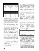
Page 12: ...rom the city cold water supply line by means of an isolating ball valve No 22 Line thermometers shall be installed in the col lector supply and return lines to allow for a sim ple diagnostic check of proper system operation On a sunny day the hot water return line should be approximately 5 12 warmer than the water in the collector supply line Compare the tem perature readings in the two line therm...

Page 13: ...TRAC TOR TO PROVIDE WATER TO YOUR FIXTURES AT NO MORE THAN 120ºF 4 9 Tank Insulation SunEarth requires that the solar storage tank must have a minimum insulation value of R 20 Most solar storage tanks now come with R 16 7 factory insulation Conventional back up elec tric water heaters have insulation values between R 12 and R 20 The R value expresses the ther mal conductivity of the insulation mat...

Page 14: ... 777B sin gle pole single throw toggle switch mounted in a standard UL listed box rated at 10 amps 125 volts DC Connect the switch only in the positive line between the photovoltaic module and the 12 volt DC circulating pump Wire the red leads from the module and the pump to the two ter minal screws on the toggle switch Wrap the stripped wires 3 4 turn clockwise under the heads of the screws witho...

Page 15: ... Flojet or equal to fill and pres surize the collector loop Connect the discharge side of the pressure pump to the upper charge faucet No 9 Place the pump suction side hose in the glycol solution Close the isolation ball valve No 10 and con nect a second hose to the lower charge faucet No 11 Place the other end of the hose in the empty bucket Open the upper charge faucet and allow the pressure fro...

Page 16: ...s Distilled or deionized water is required The HTF pH level must be maintained between 8 and 10 to minimize corrosion and glycol oxidation in the piping system 5 SYSTEM START UP PROCEDURES Throughout the installation procedures outlined in Section 4 above emphasis has been placed on the correct procedures for plumbing and wiring the components checking for plumbing leaks pressurizing the collector...

Page 17: ... for the single tank system above All three ball valves above the heaters Nos 23 24 and 25 must have the valve handles placed in the horizontal position See Figures 18c 100 Utility Power and 18d 7 ISOLATING THE MAJOR COMPONENTS AND SYSTEM SHUT DOWN PROCEDURES Your SolaRay solar water heating system is designed so that the key components can be eas ily isolated for emergency repairs or routine main...

Page 18: ...y solar water heating system and also to extend the life of the primary components 9 1 Fluid Quality It is extremely important to moni tor the quality of the Dowfrost HD HTF on a periodic basis The chemi cal composition of the heat transfer fluid may change over time System pH must be main tained between 8 and 10 to avoid damage to the collector loop and absorber plate piping The specified glycol ...

Page 19: ...ating on a sunny day and you have no hot water check the photovoltaic module and circulating pump wire connections Make sure the toggle switch is in the on position If the connections check out O K contact your installation contractor for serv ice 9 9 If the weather is poor and the auxiliary heat ing element will not fire the bright red reset but ton on the thermostat may have to be depressed to b...

Page 20: ...e tank to prevent mixing with the warm water at the top of the tank 17 Heat Exchanger Transfers heat from the solar collector loop piping by conduction to the potable water in the solar storage tank The heat exchang er is double walled and vented If a leak in the heat exchanger piping occurs there is no possibili ty of cross contamination with the potable water in your solar storage tank 18 Anode ...

Page 21: ...ars The HTF must be maintained as specified in this manual to maxi mize collector life Photovoltaic modules have design lives in excess of twenty years The solar storage tank should last 10 to 20 years in most water quality areas by periodically replacing the anode rod The 12 volt DC circulating pump generally runs 20 000 hours before the brushes or motor require replacement Like EPA mileage estim...

Page 22: ...ll be designed for 160 psig maximum operating pressure ABSORBER COATING AND PERFORMANCE CURVE A Black Chrome EC Series The absorber coating shall be black chrome on nickel with a minimum absorptivity of 95 percent and a maxi mum emissivity of 12 percent The instantaneous efficiency of the collector shall be a minimum Y intercept of 0 714 and a slope of no less than 0 7271 BTU ft2 hr F B Moderately...

Page 23: ...ation EPDM grommets shall isolate the manifold from the aluminum casing The absorber plate shall be designed for 160 psig maximum operating pressure ABSORBER COATING AND PERFORMANCE CURVE A Black Chrome IC Series The absorber coating shall be black chrome on nickel with a minimum absorptivity of 95 percent and a maxi mum emissivity of 12 percent The instantaneous efficiencey of the collector shall...

Page 24: ...absorber plate or CopperHeart ICS unit is reimbursable up to 100 in year one 75 in years two through five and 50 in years six through ten FREIGHT AND SHIPPING EXPENSES During the first year of warranty coverage SunEarth will pay the shipping costs for the new or repaired Imperial Empire SunWise or SolarStar solar collector SunBurst absorber plate or CopperHeart ICS between SunEarth and the nearest...

Page 25: ...product model and serial numbers and the installation contractor s name and phone number If you have questions regarding this warranty contact your installation contractor or SunEarth at 909 605 5610 LIMITED WARRANTY EXCEPT AS EXPRESSLY PROVIDED HEREIN THE IMPERIAL EMPIRE SUNWISE OR SOLARSTAR COLLECTOR SUNBURST ABSORBER PLATE OR COPPERHEART ICS UNIT IS PROVIDED WITHOUT WARRANTY OF ANY KIND EITHER ...

Page 26: ...4315 Santa Ana St Ontario CA 91761 Phone 909 605 5610 Fax 909 605 5613 email info sunearthinc com www sunearthinc com ...

Reviews: