background image

SUNERGY USA WORKS LLC

6

12.3 On the first solar panel, connect the positive home run cable to the positive array output

cable, and connect the negative cable to the positive cable of the second solar panel.

On the second solar panel, connect the negative cable to the positive cable of the third

solar panel. Continue until you have series connected the appropriate number of panels

for the desired voltage.

12.4 When you have made direct connections between the specified number of solar panels,

use a digital multimeter to measure the voltage and current output of the array.

12.5 Organize the cables between solar panels.

13.

Daily maintenance instructions

  13.1 Do not clean the modules without professional authorized, and ensure the appropriate facilities

to conduct security operations and aerial work with high-altitude awareness of the danger.

13.2

 Checking the glass for cracks and damage before cleaning the module.

If the modules have

been broken, do not be cleaned, and immediately inform the installer or maintainer.

13.3 Do not use cleaning components of a strong type of chemical or abrasive detergent and

disinfectant operations. To prevent serious pollution will reduce the output power. We

recommend using water to clean modules. If the animals that produce the dirt, a mild soapy

water and neutral disinfectant will be recommended.

If necessary use a soft sponge or cloth to

wipe the modules, do not force or scratch the modules hard.

Do not wear jewelry or watches

during cleaning the modules, Do not scraped off the dirt of animal from the components hard.

Over scratches cause power attenuation, and void your warranty policy. When the module of the

tilt angle is more than 15 degrees, the modules can self-clean naturally; when the component's

angle less than 15 degrees, regular cleaning is necessary.

Regular inspection mounting bracket

corrosion or not, if we find evidence of corrosion, please consult installers;

 Regularly check the

integrity of the ground terminal, but do not try to change the electrical connection, if you suspect

a loose connection, please contact the installer.

Summary of Contents for SUN160-36P

Page 1: ... s Street Ste 330 Raleign NC 27605 WAKE USA 1 1 POWER MODULE SUNERGY USA WORKS LLC Solar Photovoltaic modules consist of a series of electrically interconnected crystalline silicon solar cells Which are permanently encapsulated between a tempered glass superstrate and substrate The entire laminate is secured within an anodized aluminum frame for structural strength ease of installation and to prot...

Page 2: ...commended maximum series parallel module configurations are as follow 72 6 mono series 16 1 60 6 mono series 20 1 54 6 mono series 21 1 36 6 mono series 32 1 72 6 poly series 17 1 60 6 mono poly 20 1 54 6 poly series 23 1 36 6 mono poly 34 1 2 PERMIT Before installing your system contact local authorities to determine the necessary permit installation and inspection requirements 3 CLIMATE CONDITIO...

Page 3: ... W m 25 C cell temperature and solar spectral irradiance per ASTME 892 or irradiation of AM 1 5 spectrum Under normal conditions a photovoltaic panel may experience conditions that produce more current and or voltage than reported at Standard Test Conditions Accordingly the values of Isc and Voc marked on should be multiplied by a factor of 1 25 when determining component voltage ratings conductor...

Page 4: ... together with spring washers and flat washers in eight places symmetrical on the SUNERGY module The applied torque is about 8 Newton meters The module can t be installed using clamps It is not permitted to modify the module frame under any circumstances Recommended distance between 2 solar modules is 5mm considering linear thermal expansion of the module frames Clearance between the module frame ...

Page 5: ...each module 11 2 The module frame must be attached to a supporting structure using M8 stainless steel hardware together with spring washers and flat washers in eight places symmetrical on the module 11 3 Clearance between the module frame and mounting surface may be required to prevent the junction box from touching the surface and to circulate cooling air around the back of the module 11 4 Connec...

Page 6: ...n broken do not be cleaned and immediately inform the installer or maintainer 13 3 Do not use cleaning components of a strong type of chemical or abrasive detergent and disinfectant operations To prevent serious pollution will reduce the output power We recommend using water to clean modules If the animals that produce the dirt a mild soapy water and neutral disinfectant will be recommended If nec...

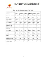
Page 7: ...330 5 335 5 340 5 345 5 350 5 355 5 Maximum system voltage V 1000 1000 1000 1000 1000 1000 Maximum Over Current Protection Rating A 15 15 15 15 15 15 Module type SUN360 72 M SUN365 72 M SUN370 72 M SUN275 60 M SUN280 60 M SUN285 60 M Voc V Tolerance 47 9 5 48 1 5 48 3 5 38 0 5 38 2 5 38 7 5 Vmp V 38 9 39 1 39 3 31 9 31 1 32 2 Isc Adc Tolerance 9 75 5 9 82 5 9 85 5 9 21 5 9 35 5 9 48 5 Imp Adc 9 25...

Page 8: ... M SUN275 54 M SUN165 36 M Voc V Tolerance 35 7 5 36 2 5 36 6 5 36 9 5 37 3 5 23 1 5 Vmp V 28 8 29 0 29 1 29 3 29 4 19 1 Isc Adc Tolerance 9 35 5 9 45 5 9 6 5 9 7 5 9 81 5 9 17 5 Imp Adc 8 85 8 96 9 1 9 22 9 35 8 62 Pmp W Tolerance 255 5 260 5 265 5 270 5 275 5 165 5 Maximum system voltage V 1000 1000 1000 1000 1000 1000 Maximum Over Current Protection Rating A 15 15 15 15 15 15 Module type SUN170...

Page 9: ...on Rating A 15 15 15 15 15 15 Module type SUN270 60P SUN265 60P SUN250 54P SUN245 54P SUN240 54P SUN165 36P Voc V Tolerance 37 20 5 37 00 5 34 80 5 34 30 5 33 50 5 23 00 5 Vmp V 31 20 31 00 28 50 28 30 28 10 18 90 Isc Adc Tolerance 9 06 5 8 94 5 9 19 5 9 05 5 8 95 5 9 16 5 Imp Adc 8 65 8 54 8 77 8 66 8 54 8 74 Pmp W Tolerance 270 5 265 5 250 5 245 5 240 5 165 5 Maximum system voltage V 1000 1000 1...

Page 10: ...SUNERGY USA WORKS LLC 10 Temperature cofefficient Temp Cofe Of Isc 0 048 C Temp Cofe Of Voc 0 30 C Temp Cofe Of Pmax 0 40 C ...

Reviews: