7790
3 10/25/16
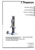
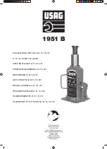
PLEASE REFER TO THE EXPLODED VIEW DRAWING IN THIS MANUAL IN ORDER TO IDENTIFY PARTS.
1. This clutch jack is designed to remove, install and transport (in the lowered position) 14
"
and 15-1/2
"
double disc clutches and/or
flywheel assemblies.
2. Determine the clutch size to be worked on. Install the (#17) 1-3/4
"
diameter spline shaft in the (#1) shaft receiver if working on a
14
"
clutch and the (#2) 2
"
diameter spline shaft for a 15-1/2
"
clutch. Secure the spline shaft to the (#1) shaft receiver with the (#32)
clip pin.
3. Install the (#25) handle in the (#26) handle receiver and turn the handle clockwise until it stops.
4. It may be necessary to bleed air out of the jack’s hydraulic system if pumping feels spongy or the jack will not pump to maximum
height without a load. Follow these steps to remove air from the hydraulic system:
a. Turn the jack’s release knob in a clockwise rotation until tight. Now turn the knob counterclockwise two full revolutions.
b. Pump the handle 15 full incremental pump strokes without a load.
c. Turn the jack’s release knob clockwise until tight and pump the jack to maximum height without a load.
d. Repeat steps a. through c. until all air is purged from the system.
OPERATING INSTRUCTIONS
This is the safety alert symbol used for the
OPERATING INSTRUCTIONS
section of this manual to alert you to potential
personal injury hazards. Obey all instructions to avoid possible injury or death.
1. Assess the work to be done and determine how much clearance is required under the vehicle in order to roll the jack with
clutch under the vehicle. Lift the vehicle to the desired work height in accordance with the vehicle manufacturer’s recommended
procedure and immediately after lifting the vehicle, support it with a match pair of jack stands that have the appropriate capacity
rating. Make sure the setup is stable. Determine which spline shaft is required to do the job and install it in the shaft receiver.
2. Position the tilting saddle so the spline shaft is vertical to the floor. Roll the jack under the vehicle and in line with receiving the
clutch. If there is not enough clearance it may be necessary to lift the vehicle’s front end higher and readjust the jack stand
columns accordingly.
3. Once the jack is positioned below the clutch, rotate the tilting saddle so the spline shaft is parallel with the floor. Close the
release valve by turning it clockwise until it stops and proceed to pump the jack slowly so the spline shaft is in line with the
clutch splines. Adjust the angle of the spline shaft so that it matches the angle of the clutch assembly by rotating the saddle
adjustment screw.
4. Match the free end of the spline shaft with the opening of the clutch assembly by pumping and moving the jack in position.
Rotate the spline shaft until the splines match with the splines in the clutch assembly. It may be necessary to adjust the spline
angle so the clutch assembly will slide right on to the jack’s spline shaft. Unbolt the clutch from the flywheel and slide the clutch
onto the jack’s spline shaft.
5. Pull the clutch jack away from the flywheel and slowly turn the jack’s release valve knob in a counterclockwise direction until the
clutch is lowered all the way down. Now position the clutch so the jack’s spline shaft is vertical to the floor. The jack and clutch
should provide a low enough profile to roll them from underneath the vehicle.
6. Follow the vehicle manufacturer’s clutch installation procedure and these operating instructions in the proper order to install
the clutch.
PREVENTATIVE MAINTENANCE
This is the safety alert symbol used for the
PREVENTATIVE MAINTENANCE
section of this manual to alert you to
potential personal injury hazards. Obey all instructions to avoid possible injury or death.
1. Always store the jack in a well protected area where it will not be exposed to inclement weather, corrosive vapors, abrasive dust,
or any other harmful elements. The jack must be cleaned of water, snow, sand, grit, oil, grease or other foreign matter before
using.
2. The jack must be lubricated periodically in order to prevent premature wearing of parts. A general purpose grease must be
applied to the threads on the extension screw. Do not lubricate any portion of the lift saddle and make sure the saddle is free
from grease, any kind of lubricant, or debris before using the jack. Jacks found to be defective due to worn parts resulting from
inadequate or no lubrication are not eligible for warranty consideration.
3. It should not be necessary to refill or top off the reservoir with hydraulic fluid unless there is an external leak. An external leak
requires immediate repair which must be performed in a dirt-free environment by qualified hydraulic repair personnel who are
familiar with this equipment. Authorized Service Centers are recommended. IMPORTANT: In order to prevent seal damage and
jack failure, never use alcohol, hydraulic brake fluid, or transmission oil in the jack. Use hydraulic jack oil, Chevron Hydraulic Oil
AW ISO 32 or its equivalent Unocal Unax AW 150.
4. Every jack owner is responsible for keeping the jack label clean and readable. Use a mild soap solution to wash external surfaces
of the jack but not any moving hydraulic components.
SETUP
7790
CAPACITY: 300 LB.
CLUTCH JACK


