background image

2

Installation Manual

16. To prevent electric shock

, do not use this polarized 

plug with an ex ten sion cord, receptacle or other outlet 
unless the blades can be fully inserted to prevent blade 
ex po sure.  

Pour préevenir les chocs électriques ne pas utiliser cette 
fi che polariseé avec un prolongateur, un prise de courant 
ou une autre sortie de courant, sauf si les lames peuvent 
être insérées à fond sans laisser aucune parIVe à décou-
vert.

17. Grounding or Po lari za tion

 — Pre cau tions should be 

taken so that the grounding or polarization means of the 
Com po nent is not defeated.

This apparatus does not exceed the Class A/Class B (which-
 ev er is ap pli ca ble) limits for radio noise emis sions from digital 
apparatus as set out in the radio interference regulations of 
the Canadian Department of Com mu ni ca tions.

ATTENTION — Le présent appareil numérique n'émet pas 
de bruits radioélectriques dépassant las limites applicables 
aux appareils numériques de class A/de class B (selon le 
cas) prescrites dans le règlement sur le brouillage radioé-
lectrique édicté par les ministere des com mu ni ca tions du 
Canada.

WARNING

 – TO REDUCE THE RISK OF FIRE OR ELECTRIC SHOCK, DO 

NOT EXPOSE THIS AP PLI ANCE TO RAIN OR MOIS TURE.

CAUTION:

 TO PREVENT ELECTRIC SHOCK, MATCH WIDE BLADE OF 

PLUG TO WIDE SLOT, FULLY INSERT.

ATTENTION:

 POUR 

É

VITER LES CHOCS 

É

LECTRIQUES, INTRO- DU-

IRE LA LAME LA PLUS LARGE DE LA FICHE DANS LA BORNE CORRE-
SPONDANTE DE LA PRISE ET POUSSER JUSQU’AU FOND.

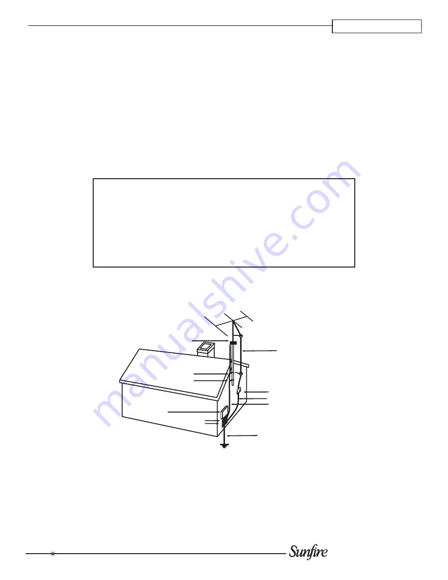
EXAMPLE OF ANTENNA GROUNDING ACCORDING TO NATIONAL

ELECTRICAL CODE INSTRUCTIONS CONTAINED IN ARTICLE

810–“RADIO AND TELEVISION EQUIPMENT”

GROUND CLAMP

GROUNDING
CONDUCTORS
(NEC SECTION 810-21)

ANTENNA
LEAD IN WIRE

POWER SERVICE GROUNDING
ELECTRODE SYSTEM
(NEC ART 250, PART H)

SERVICE

ENTRANCE

EQUIPMENT

GROUND CLAMPS

GROUND CLAMPS

ANTENNA DISCHARGE UNIT
(NEC SECTION 810-20)

NEC NATIONAL ELECTRICAL CODE.

NOTE TO CATV INSTALLER
This reminder is to call the CATV system installer's attention to Article 820-40 of the NEC that provides guide-
lines for proper grounding and in particular, specifies that the cable ground shall be connected to the grounding
system of the building as close to the point of cable entry as practical. 
OUTSIDE ANTENNA GROUNDING
If an outside antenna is connected to the receiver, be sure the antenna system is grounded so as to provide
some protection against voltage surges and built-up static charges. Article 810 of the National Electrical Code,
ANSI/NFPA 70, provides information with regard to proper grounding of the lead-in wire to an antenna-discharge
unit, connection to grounding electrodes, and requirements for the grounding electrode. See Figure above. 

SAFETY

Summary of Contents for TGM-100 Server

Page 1: ...Theater Grand Media Player TGM 100 Server TGM 100C Client ...

Page 2: ......

Page 3: ...rug or similar surface that may block any ventilation openings or placed in a built in installation such as a bookcase cabinet or closed equipment rack that may impede the flow of air through ventilation openings 11 Power Sources The apparatus should be connected to a power supply only of the type described in these op eration instructions or as marked on the apparatus 12 Power Cord Protection Pow...

Page 4: ... ELECTRIC SHOCK MATCH WIDE BLADE OF PLUG TO WIDE SLOT FULLY INSERT ATTENTION POUR ÉVITER LES CHOCS ÉLECTRIQUES INTRO DU IRE LA LAME LA PLUS LARGE DE LA FICHE DANS LA BORNE CORRE SPONDANTE DE LA PRISE ET POUSSER JUSQU AU FOND EXAMPLE OF ANTENNA GROUNDING ACCORDING TO NATIONAL ELECTRICAL CODE INSTRUCTIONS CONTAINED IN ARTICLE 810 RADIO AND TELEVISION EQUIPMENT GROUND CLAMP GROUNDING CONDUCTORS NEC S...

Page 5: ...TER 1 Read the Safety Instructions care fully before connecting and using your TGM 100 Chapter 1 is a general introduction to the features and details of your TGM 100 Chapter 2 shows the proper way to connect and install your TGM 100 Chapter 3 describes how to config ure the system for proper operation Chapter 4 describes how to install third party software applications and software updates Chapte...

Page 6: ...fferent room from the Digital Video display Without proper planning of the TGM 100 configuration during installation configuration may be problematic There are a number of options available in these circum stances These include 1 Temporarily connect an HDMI display directly to the TGM 100 s Digital Video connector using short cables and configure the TGM 100 using the remote control 2 Ensure that ...

Page 7: ...100 is to be installed in a rack please see the diagram below for a guide to correct positioning TGM 100 Server TGM 100 Clients Uninterruptible Power Supply UPS Fan Amplifiers Heat Generating Devices Leave space between TGM 100 and other components TGM HDC iSCSI Storage Device ...

Page 8: ...on to turn the TGM 100 On press it again to turn the unit Off 2 DISC PLAYER CDs and DVDs should be inserted with the label side facing up 3 EJECT BUTTON Pressing the EJECT button ejects the disc 4 IR WINDOW The front panel IR Window allows remote control information to be transmitted to the TGM 100 ...

Page 9: ...ch the TV to the relevant AUX input to display the picture 6 S VIDEO OUT Connect the S VIDEO output of the TGM 100 to the S VIDEO input of a suitable PAL or NTSC TV to display the TV User Inter face You may also need to switch the TV to the relevant AUX input to display the picture 7 ANALOG AUDIO OUT This analog audio output should be connected to the input jacks of a pre amplifier receiver or who...

Page 10: ...l storage devices Output channels from the TGM 100 may be connected to a multi room control system so that they can be distributed to different rooms around the home In order for the TGM 100 TVs Amplifers Speakers Video Audio TGM 100C Clients Max 6 Gigabit Ethernet LAN Gigabit Switch TGM HDC iSCSI External Storage TGM HD1 eSATA Storage LAN eSATA Cable TGM 100 Server Video Audio TV Amplifer Speaker...

Page 11: ...e video mode is set to Auto the Component Video output will be enabled Digital Coaxial Connections A V Receiver TGM 100 Coaxial Digital Cable A V Receiver TGM 100 Optical Digital Cable Digital Optical Connections TGM 100 HDMI Cable A V Receiver HDMI IN 1 HDMI IN 2 HDMI OUT HDMI Connections Audio Connections The digital output provides bit perfect audio output without the use of a rate converter Wh...

Page 12: ...ut is connected to an audio routing device such as an A V Receiver or Multi Room Controller using stereo RCA audio cables Note 5 1 Digital Audio Outputs are converted to 2 Channel PCM when Analog Connections are enabled Note When 2 channel PCM outputs are enabled 5 1 Dig tal surround effects are disabled Note Discrete IR codes are available when programming touchpanels keypads etc in whole house a...

Page 13: ...r can be connected to an A V Receiver with HDMI switching capabilities then to the TV If connecting the HDMI output directly to a TV make sure to connect the Digital or Analog Audio outputs to an A V Receiver or Multi Room Controller as described previously If connecting the HDMI output to an A V Receiv er that supports audio over HDMI additional Audio connec tions are unnecessary HDMI video has a...

Page 14: ...o Cable TV COMPONENT IN IN OUT COMPONENT VIDEO Component Video Cable Component Video to A V Receiver Connections Component Video Switcher TGM 100 Component Video Cable TV COMPONENT IN COMPONENT VIDEO INPUTS Y P B P R Y P B P R 1 2 3 4 1 2 3 4 COMPONENT VIDEO OUTPUTS Y P B P R Y P B P R Component Video Cable Component Video to Component Video Switcher Multi Room Controller Connections switching cap...

Page 15: ...eo switching capabilities Because S Video has a TGM 100 S Video Cable TV COMPONENT IN S VIDEO IN S Video to TV Connections TGM 100 S Video Cable A V Receiver S VIDEO IN 3 S Video Cable TV COMPONENT IN S VIDEO IN S VIDEO IN 2 S VIDEO IN 1 S VIDEO OUT S Video to A V Receiver Connections relatively short distance restriction it is not recommended to use this format for Multi Room systems instead use ...

Page 16: ... IN VIDEO IN Composite Video to TV Connections TGM 100 A V Receiver VIDEO IN 3 VIDEO IN 2 VIDEO IN 1 VIDEO OUT Composite Video Cable TV COMPONENT IN S VIDEO IN VIDEO IN Composite Video to A V Receiver Connections connect directly to a TV an A V Receiver a Composite Video Switcher or a Multi Room Controller Long runs from the head end location should be wired using RG 6 or RG 59 coaxial cable with ...

Page 17: ...0 s HDMI output connected to a High Definition TV The HDMI output can be used simultaneously with the S Video Component Video and or Composite Video outputs depending on the application When the HDMI output is being utilized the DVI output should not be connected The following chart summarizes the video outputs and their compatibility Output Option 1 Option 2 Option 3 HDMI Primary DVI Secondary To...

Page 18: ...ut allows the homeowner to view and control the TGM 100 with the convenience of full touchscreen functionality in any room of the house Full installation details and specifications are available in the TGM DVC Installation Manual To connect a touch panel to the TGM 100 using a TGM DVC Composite Video Converter Connect the USB cable included with the TGM DVC between one of the USB ports on the TGM ...

Page 19: ...gabit switch Required Ethernet devices include 1 Broadband Modem Connects to the Internet and to the Router or Switch 2 Router Connects to the Broadband Modem and to each component of the network In many installations the Router will connect to an Gigabit Ethernet Switch 3 Gigabit Ethernet Switch Connects to the Broadband Modem or Router and to the TGM 100 Server TGM 100 Client TGM HDC and compute...

Page 20: ...GM 100 Server only TGM 100 Clients only sup port external storage via a TGM 100 Server 3 Set the Power Switch Off Auto On to the middle Auto position for Automatic power control This allows the TGM HD1 to power On and OFF when the TGM 100 powers On and Off 4 Turn on the TGM 100 It will automatically recognize the TGM HD1 as soon as both units are fully operational Note Only one eSATA Storage Deviv...

Page 21: ...id Green OK Blinking Problem Detected Solid Red Failure 4 ETHERNET PORT CONSOLE This port is used for managing settings on the TGM HDC 5 ETHERNET PORT 1 This port is used for data streaming to TGM 100s and TGM 100Cs 6 ETHERNET PORT 2 This port is not currently used 7 RS 232 PORT MODEM This port connects to the U P S Use the cable that is supplied with the U P S 8 RS 232 PORT CONSOLE This port has ...

Page 22: ...ower and the TGM HDC is turned OFF 2 Plug both of the TGM HDC s power connectors into the UPS 3 Plug the TGM 100 s power cable into the UPS as well 4 Connect the Serial Cable RS 232 that came with the UPS to the Serial port on the UPS and to the port labelled Modem on the TGM HDC 5 Connect the UPS to AC power 6 Turn On the UPS 7 Turn On the TGM HDC and TGM 100 RS 232 Serial Cable AC Power Cables S...

Page 23: ... the rear of this guide for information about using Display Help to configure the TGM 100 s video settings System Control There are a number of different ways to control the system The choice of controller depends on the type of installation and the control system being integrated Remote Control The TGM 100 is supplied with a remote control that can be used to control it via infrared Note The TGM ...

Page 24: ...select the Movies icon you are taken to the Movies screen where you may select from all the movies that have been recorded onto the system Movies may be displayed as a list or by cover art and may be grouped by Titles Actors Directors Ratings Genres and Years Disc The Disc icon provides access to a CD or DVD that is currently in the Disc Tray CD options include Play Disc Tracks Record Disc and Rec...

Page 25: ...en recorded On line Update allows you to check for periodic software updates to improve or update functionality of the TGM 100 User Settings provides access to Display Settings Sys tem Information and Recording Settings Each of these functions are detailed later in this manual Installer Settings provides access to advanced functions and setting needed by the installer of the unit Selecting this op...

Page 26: ...c Setup func tions such as Media Lookup On line Update etc Most commonly used functions of the TV UI are found on the Home Screen shown above Touch Panel UI The Touch Panel UI provides a method to control the TGM 100 from touch panels located throughout the home The TGM 100 is designed to work with all current ELAN wired or wireless touch panels and provides full control over the system Admin UI T...

Page 27: ...ttings and press OSelect The Display Settings screen is displayed Primary Display Configuration The Primary Display Configuration can be set to Auto HDMI Component or S Video Composite The Auto setting is recommended This will select the best display quality of the connected outputs Select a differ ent mode only if non standard configurationis desired For example when using a video switcher or com...

Page 28: ...nalog Settings TV Mode The TV Mode screen allows you to choose the best available video display when utilizing the Analog video outputs Typically this will be set to the highest setting your TV will display Output Format Typically you will configure this setting to Auto Use the other settings when using non standard installations like video switchers etc Auto Switching For most televisions Auto Sw...

Page 29: ...communications between these devices occur over the network and their IP addresses must remain con stant for this to take place Note You should obtain the IP addresses you need from your Network Administrator Do not just change it to Static and re use the IP address issued by the DHCP server DHCP IP addresses can expire after a variable amount of time and the DHCP Server will expect to be able to ...

Page 30: ...at can be run to check the TGM 100 s connection to the network and the Internet Navigate to the Admin UI and display the Settings screen as described previously From the Assigned Ethernet Settings screen press the äTest button The Ethernet Tests screen is displayed Press the MStart button to run the tests The TGM 100 will now run a number of Ethernet tests After a short while any failures will be ...

Page 31: ...aly or the Admin UI on the Web UI or the Main TV display The Web version of the Touch Panel UI is primarily accessed when using ELAN wireless touch panels Accessing Installer Settings Through the Web UI Once the IP Address is known and you are able to access the TGM 100 s Web UI it is possible to access the Install er Settings menu via the home PC Open a web browser as previously described Enter t...

Page 32: ...ted Should the TGM 100 detect any inconsistency in the TGM HD1 setup during startup it will correct this automatically and then restart itself using the new configuration Connecting Ethernet Storage TGM HDC This section covers the basic information needed to get the Sunfire TGM HDC connected and functioning with the TGM 100 Connect the TGM HDC device as described previously Connect a PC to the net...

Page 33: ...d Confirm the new IP Address by looking on the front panel display of the TGM HDC It should now display the value that you just added Type the new IP Address into the web browser You may be prompted to restart the browser before typing in the new address You have now configured a Static IP Address for the TGM HDC Mail This section describes how to set up mail preferences in order to receive email ...

Page 34: ... Enter the IP Address found on the Display Window found on the front of the TGM HDC followed by the Admin User Name admin and the Admin Password en91n3 Use no spaces and separate each with a comma For example 192 168 0 198 admin en91n3 For systems with multiple TGM HDC iSCSI devices use a semicolon without spaces between the credentials of each device For example 192 168 0 198 admin en91n3 192 168...

Page 35: ...utomatically Erasing All Media CAUTION This process will permanently delete all your albums and videos and cannot be reversed From the Reset System screen shown above select M Clear Content A Confirm screen will be displayed Press O Yes to confirm that you wish to proceed The Enter Password screen will be displayed Enter the System Password which is ResetMyMedia Note that the password is case sens...

Page 36: ...to one of these ports and a USB mouse into the other If you want to plug a USB memory stick in as well you can use a USB hub to increase the number of ports While on the Home Screen type the following case sensitive password on the USB keyboard en91n3 Left Ctrl A pop up window will appear on the television user interface If the above pop up window does not appear re type the password carefully ens...

Page 37: ...ction below entitled Configuring an Application for instructions about how to do this at a later time When the installation is complete you will need to leave Engineering Mode Click on Engineering Menu to show the drop down menu Select Leave Engineering Mode Save Changes from the drop down menu Configuring Applications You may want to configure an application to prevent it from displaying future m...

Page 38: ... the prompts to complete the removal process If you are prompted by the installer to reboot then do so The unit will automatically reboot into Engineering Mode When the removal process is complete you will need to leave Engineering Mode Leaving Engineering Mode Click on Engineering Menu to show the drop down menu Select Leave Engineering Mode Save Changes from the drop down menu ...

Page 39: ...nsure contact the network administrator or consult an IT professional Cat5e Cat6 It is important to use Cat5e or Cat6 Ethenet cables throughout the TGM 100 s network when installing a TGM HDC Utilizing other types of cabling can cause improper operation Determining Static Ethernet Settings If you are connecting the TGM 100 to an existing network and you want to configure Static Ethernet settings y...

Page 40: ...teries are dead Change the batteries in the remote control Resetting the UI Should the TGM 100 s UI become unresponsive the system does not respond to IR commands the following pocedure may be used to reset the UI without having to reboot the ystem Using the remote control simultaneously press the Audio Server and the OSelect buttons Hold both buttons until the Audio Server button remains solidly ...

Page 41: ...Output Resolution 480i 1080i DVI Output Connector DVI Jack Output Resolution 480i Audio Outputs Analog Outputs Output Level 2V RMS Output Impedance 600 W Connector RCA Jack Digital Outputs Optical Output Connector Toslink Coaxial Output Level 500mVp p 75 W Coaxial Output Connector RCA Jack Analog Audio Characteristics typical Frequency Response 20Hz to 20kHz 0 5dB S N ratio 1KHz 100dB A weighted D...

Page 42: ...er expenses which may be incurred in connection with repair or replacement Except as may be expressly provided and authorized in writing by Sunfire Sunfire shall not be subject to any other obligations or liabilities what soever with respect to equipment manufactured by Sunfire or services rendered by Sunfire THE FOREGOING WARRANTIES ARE EXCLUSIVE AND IN LIEU OF ALL OTHER EXPRESSED AND IMPLIED WAR...

Page 43: ......

Page 44: ...P N 9900979 REV A ...

Reviews: