9
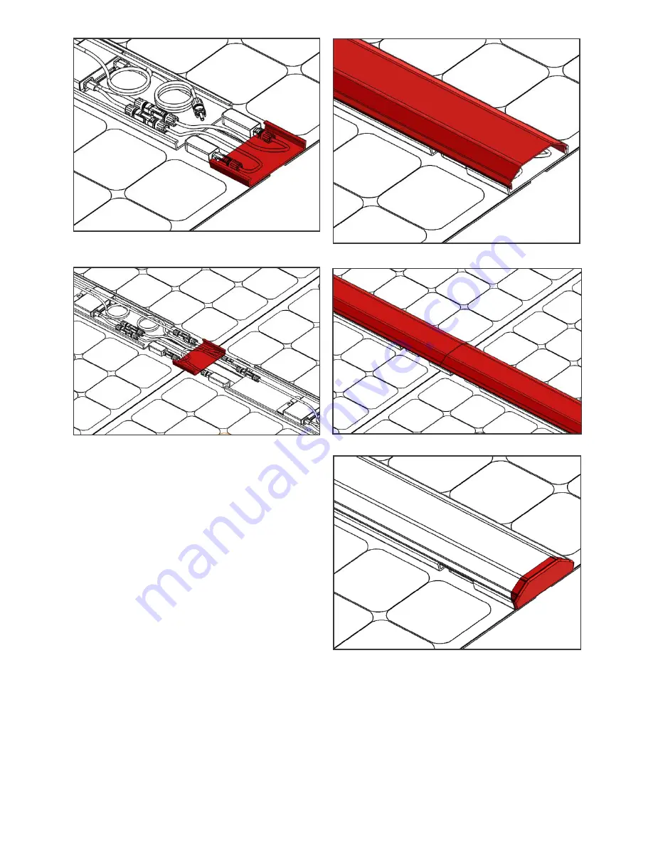
Figure 7 – Install couplers at the ends of rows.
Figure 9 – Align top cover to end of row.
Figure 10 – Top covers joined at coupler.
Figure 11 – Cement the end cap to the top cover
Figure 8 – Install couplers across every 3 modules
Align the top cover to the edge of the row and
snap it down to the wire tray as shown in Figure
9. Repeat this process across the row ensuring
there are no gaps between the covers at the
joining couplers as shown in Figure 10. Measure
and cut the last cover to the required length prior
to installation.
Finally, install the end caps to the top covers at
both exposed ends of the row as shown in Figure
11. Use an outdoor rated PVC cement to join the
end cap to the top cover. Do not cement the end
cap to the coupler. Doing so will make removing
the top cover difficult when servicing the system.
For additional information and a photo
walkthrough of the installation process, refer to
the “FLEX60 Installation Supplement” document.
Grounding
Per its certification, the Sunflare FLEX60 module
is not to be grounded. It is double insulated
and has no exposed metal components. Ensure
you use only no conductive polymeric wire
management devices and components within the


