background image

light starts operating. 


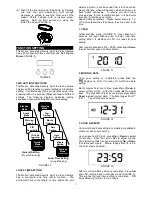
Provisionally turn the LUX control knob to the edge at 

the  moon  (dusk)  position  (FIGURE  31).    In  this 

provisional  setting  mode,  the  Motion  Sensor  remains 

inactive during daylight.    At dusk when you find it is the 

LUX  level  desired  for  operation,  simply  set  the  LUX 

control knob to the position which will become active as 

daylight declines. 


Note:

 The LUX setting range is between 20 LUX to 200 

LUX. 

FIGURE 31 


CHOOSING A MOUNTING LOCATION


  For the best results, fix the unit on a solid surface, 

2~2.5m above the ground. 

  Avoid  aiming  the  unit  at  pools,  heating  vents,  air 

conditioners  or  objects  which  may  change 

temperature rapidly. 

  Do not allow sunlight to fall directly on the front of 

unit. 

  Try to avoid pointing the unit at trees or shrubs or 

where the motion of pets may be detected. 

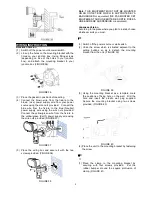
  The  motion  sensor  is  more  sensitive  to  objects 

moving across its field of view.    It is less sensitive 

to  an  object  moving  directly  towards  the  sensor 

head. (FIGURE 32). 

head. (FIGURE 

head. (FIGURE 

head. (FIGURE 

head. (FIGURE 

head. (FIGURE 

head. (FIGURE 


SENSITIVITY TO MOTION 

FIGURE 32 


SAFETY PRECAUTIONS 


  Do  not  install  the  MOTION  ACTIVATED 

SECURITY  LIGHT  &  VIDEO  CAMERA  when  it  is 

raining.


  Be  sure  to  switch  off  power  source  before 

installing. 

  To avoid fire or burn hazards: 

Allow  fixture  to  cool  before  touching.    The  bulb 

and the fixture operate at high temperatures. 

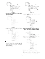
  The  halogen  bulb  installed  must  parallel  to  the 

ground as shown in the below drawing. (FIGURE 

33) 


FIGURE 33 

IMPORTANT 

Installation  must  be  performed  by  skilled 

technicians  who  are  informed  about  the  standards 

and technical requirements of the appliance and its 

proper installation. 


Check  your  local  codes  as  they  apply  to  your 

situation. If the house wiring is of aluminum, consult 

with an electrician about proper wiring methods. 


Before proceeding with the installation, TURN OFF 

THE POWER TO THE LIGHTING CIRCUIT AT THE 

CIRCUIT  BREAKER  OR  FUSE  BOX  TO  AVOID 

ELECTRICAL SHOCK.


INSTALLATION


A  drill  and  a  screwdriver  are  needed  for  installation. 

Select  a  location  for  the  unit  based  on  the  coverage 

angles as shown in FIGURE 34. (110º at 8m range) 


FIGURE 34 


Install  a  wall  switch  adjacent  to  the  power  source. 

(FIGURE  35).    This  will  help  you  operate  MOTION 

ACTIVATED  SECURITY  LIGHT  &  VIDEO  CAMERA 

with ease. 


Summary of Contents for MOTION ACTIVATED SECURITY LIGHT & VIDEO CAMERA

Page 1: ... During the day the built in photocell sensor saves electricity by deactivating the light Built in SD card slot for additional storage accept memory storage up to 32GB Pre recorded function allows you to trace event happening and customized sound recording is available at your disposal The MOTION ACTIVATED SECURITY LIGHT VIDEO CAMERA is compatible with O Net product and can be controlled by remote...

Page 2: ...To insert a SD card 1 Insert the wrench provided in screw pack 4 56 4 0 4 7 5 7 0 9 9 7 4 0 4 4 9 0 2 5 1 0 8 0 7 2 89 4 48 2 0 5 49 5 7 9 8 7 54 9 3 5 9 5 50 8 7 3 0 8 8 0 4 FIGURE 4 FIGURE 4 2 Insert SD card into the card slot FIGURE 5 FIGURE 5 3 Refit the cover and fasten the screw clockwise FIGURE 6 FIGURE 6 4 Once Motion Activated Security Light Video Camera is powered up it will detect the e...

Page 3: ...eps below to set up exact local time 1 YEAR Under standby mode FIGURE 3 press Set for 3 seconds and light flashes once to enter local time setting When displays on LCD it is ready for year setting Year range is between 2010 2099 press Up or Down to select correct year as shows below FIGURE 11 2 MONTH DATE Once year setting is completed press Set the displays on LCD it is ready for month and date s...

Page 4: ...ails of four scene modes 1 1 Scene 1 It s all armed mode FIGURE 15 Once the PIR detects a motion the camera and light turns on microphone starts recording and warning sound plays for 10 seconds FIGURE 15 Ambient Light Function Day Night Camera MIC On On Warning Speaker On On Light On On 1 2 Scene 2 Once PIR detects a motion the camera and microphone starts recording Depending on the ambient light ...

Page 5: ...recording you can record your own audio warning FIGURE 23 Built in microphone is used for video recording and for creating your unique warning sound To create your unique sound warning sound 3 4 a Select warning sound 3 or 4 b Press Set for 3 seconds the light flashes once implies the Motion Activated Security Light Video Camera is ready for recording c Wait for 5 seconds LCD occurs with REC the r...

Page 6: ...RF signal is received The unit can learn up to 12 ID codes If you wish to clear ID codes please also enter ID code learning mode Thirty seconds countdown start press Set for 6 seconds Please note once ID code clearing is executed all ID codes recorded in the unit will be cleared To ensure learning clearing is successful you can use the remote controller to switch between scenes Please refer to the...

Page 7: ...URE head FIGURE SENSITIVITY TO MOTION FIGURE 32 SAFETY PRECAUTIONS Do not install the MOTION ACTIVATED SECURITY LIGHT VIDEO CAMERA when it is raining Be sure to switch off power source before installing To avoid fire or burn hazards Allow fixture to cool before touching The bulb and the fixture operate at high temperatures The halogen bulb installed must parallel to the ground as shown in the belo...

Page 8: ...with the two screws provided FIGURE 38 FIGURE 38 Note THIS EQUIPMENT MUST NOT BE MOUNTED ON AN OUTLET BOX WHICH IS SUPPORTED BY A BAR HANGER or equivalent NE PAS MONTER CET ÉQUIPEMENT SUR UNE BOÎTE DE SORTIE FIXÉE À UNE BARRE DE SUSPENSION or equivalent Japanese Version According to the place where you plan to install choose whichever suits you most 1 Switch off the power source or wall switch 2 U...

Page 9: ...r bumper around the square protrusion of clamp FIGURE 44 FIGURE 44 2 Insert the pole band through the two holes on the clamp FIGURE 45 FIGURE 45 3 Measure the required length of pole band to be used Fold up unused pole band FIGURE 46 FIGURE 46 4 Put the unit on the pillar and connect two ends of pole band accordingly FIGURE 47 FIGURE 47 European Version 1 Switch off the power source or wall switch...

Page 10: ...vated Security Light Video Camera connected to AC power TROUBLESHOOTING Light does not turn on Confirm that you have made a correct wiring connection Make sure that the bulb has not burned out and is installed correctly Warning Sound is on after powering up SD card is not inserted PIR and LUX is not working Do not allow sunlight to fall directly on to the front of the unit Warning sound and video ...

Page 11: ...his equipment does cause harmful interference to radio or television reception which can be determined by turning the equipment off and on the user is encouraged to try to correct the interference by one of the following measures Reorient or relocate the receiving antenna Increase the separation between the equipment and receiver Connect the equipment into an outlet on a circuit different from tha...

Reviews: