9
FIGURE 41
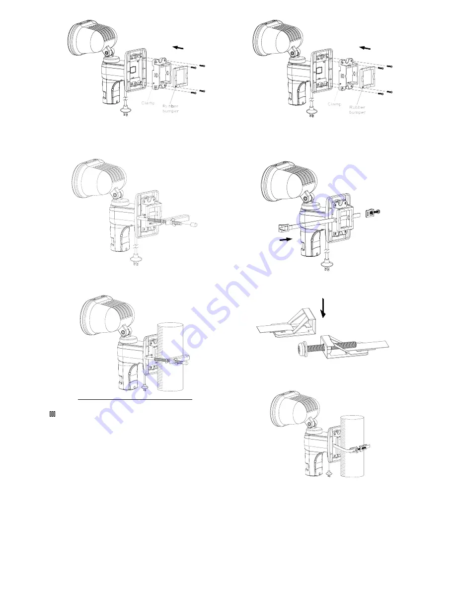
(2) Insert the L shaped holder through the two holes on
the clamp. (FIGURE 42)
FIGURE 42
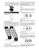
(3) Using the thumb nut on the L shaped holder, fasten
the unit on the pillar. (FIGURE 43)
FIGURE 43
@
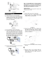
(1) Place the clamp to the mounting bracket by
securing with four screws provided. Put the
rubber bumper around the square protrusion of
clamp. (FIGURE 44)
FIGURE 44
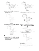
(2) Insert the pole band through the two holes on the
clamp. (FIGURE 45)
FIGURE 45
(3) Measure the required length of pole band to be
used. Fold up unused pole band. (FIGURE 46)
FIGURE 46
(4) Put the unit on the pillar and connect two ends of
pole band accordingly. (FIGURE 47)
FIGURE 47
European Version
(1) Switch off the power source or wall switch.
(2) Remove the wall box then unscrew one of the
screws on the pressure block. (FIGURE 48)


