background image

5

6

6.Mechanical Part Installation and Adjustment

6.1. Installation of cabinet

Please select the correct type of barrier ate according the specifications

of the place, and then fix the barrier cabinet with expansion bolts.

(refer to Figure 3)

6.2. Spring selection, installation and adjustment

The barrier gate is well-adjusted before delivery. If need to cut the

boom shorter, please re-adjust the spring balance to ensure the

smooth operation of the barrier. Also you can adjust the speed to

slower or faster when arm made longer or cut shorter

6.2.1. Spring selection

The length of spring prevails in kind, designing change without

notice. The spring selection please refer to the spring selection

table in the

Appendix I

of the Manual or which sticks on the door

of the barrier cabinet.

6.2.2. Spring installation, dis-assembly and replacement

Dismantlement steps: Keep the boom at vertical (open) position, see

figure1, loosen the spring fixing nuts on the bottom of the spring by

adjustable or 8

th

spanner, unscrew the fastening wing nuts in the

bottom of the spring by manual, then take off the spring.The steps for

installation and dis-assembly the spring are the opposite.

6.2.3. Spring force adjustment

When power off, adjust the springs balance to make sure the arm will stay

in the angle 45-60 degrees towards the horizontal, and not going down or

going up, which mean the spring force is well balanced.
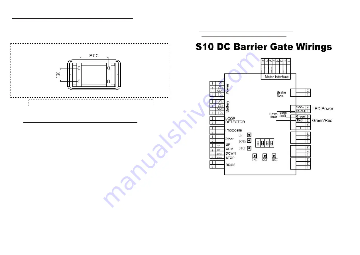
7.

Controller Wiring and Instructions

7.1.

Controller interface explanations

(Figure 4)

All the electrical connections are done before delivery. The necessity

is to connect the power and grounding connection. Explanations and

instructions for the main function interfaces and indicator light is as

following:

7.1.1. 220V/110V Power supply DIP switch in power supply:

This barrier motor supports 24VDC power input, and controller support

12V DC power input. There are two power supplies, one is 220V or

110V input(by DIP switch) while output is 24V DC, and another input is

110~220V AC while output is 12V DC. So one is for motor power

supply, and another is for control board power supply. the DIP switch is

Expansion Bolts

Press bars

(According to the supplementary size)

(According to the supplementary size)

(Figure 3)

Summary of Contents for S10

Page 1: ...Operating Instructions DC Servo Barrier Gate S10 SFMCU MicroDrive V1 0 ...

Page 2: ... Introduction SUNFRE S10 DC Brushless Servo motorized barrier gate the newly designed maintenance free with exclusive SFMCU MicroDrive unit offers 100 more torque 100 duty are the fastest toll barriers available with an opening time as fast as 0 6 seconds Opening speed is adjustable from 0 6s 0 9s to 6s or more This barrier redefines performance in non stop toll applications It is the ideal soluti...

Page 3: ...cess Reader or Push button or remote controller can be used to trigger the barrier gate to open via a simply dry contact signal After delay timer elapsed barrier gate will close automatically by itself in a certain time optional function 3 8 USER FRIENDLY Motorized arms provide comfortable passage while maintaining a high level and high density of car flow management such as in toll gate 3 10 AUTO...

Page 4: ...nscrew the fastening wing nuts in the bottom of the spring by manual then take off the spring The steps for installation and dis assembly the spring are the opposite 6 2 3 Spring force adjustment When power off adjust the springs balance to make sure the arm will stay in the angle 45 60 degrees towards the horizontal and not going down or going up which mean the spring force is well balanced 7 Cont...

Page 5: ...signal disappeared boom will auto falling to closed 7 1 9 RS485 interface This interface is used for communication between computer and SFMCU control unit We provide SDK for customers to develop software to receive barrier gate status and control barrier gate operations 7 1 10 Battery interface This interface is used for battery the battery can be used to keep barrier gate working normal when powe...

Page 6: ...below items and situations are not included in the range of free service 10 4 1 The user does not follow the instruction and cause any damage of the product 10 4 2 The power supply is not stable over the range of permitted voltage or not accordant to safety electric using standard 10 4 3 The user installs or uses the product in wrong methods cause damage to the appearance of product 10 4 4 Natural...

Page 7: ...ttom port is state 0 Empty is state X The code as below is 10XX0X1X Warning please take out the battery before coding Appendix III Wiring Diagram for R G Light Interface Appendix IV Wiring Diagram for up and down limit output No need Power Boom Length Meter M Spring Diameter Φ mm Suggested max speed Straight Boom Link Hole Selection 2 L 2 5 empty 3 5 0 6 4 L 3 empty 4 5 0 9 4 5 L 4 3 5 4 5 1 2 6 L...

Page 8: ...the speed controlled vice verse Default value is 5 DP07 Max braking strength when closing 0 10 The strength of braking when closing DP08 Default DP10 Opening angle 0 100 Horizontal degree is 0 when power on barrier gate will auto close to find 0position open to position degree is about 90 degrees Sometimes the degrees will more than or less than because of mechanical parts matching or precision is...

Page 9: ...CHAS CHACK SENSOR Sensor check E PL ERROR PULSE Motor Default Phase E CS Gate operation overtime RUNX X is the system operation Mode and the Setting Value of LP02 System Normally Operating dPXX Menu Driven Display NPXX no User Menu Display P H Dates resuming to be Default Value P F Dates resuming Default Value NOPR NO POWER Opening when no power TEST Gate self testing INXX IN NUM xxthe entering ve...

Reviews: