background image

9

10

two screws on balance rotating arm.

8.2 Vertical adjustment

After 8.1 finished, power on(make sure arm installed), after system

started, press ‘UP’ button to check the vertical position. If not, please

follow menu settings to adjust DP10. For example, barrier arm not full

90 degrees open, increase the value of DP10. If open more than 90

degrees, decrease the value of DP10 too, setting details please refer to

appendix VI.

9.

Working Codes meanings and error code solutions

9.1. When power-on, press “UP” or “DOWN” button, there is no

reaction on the boom.

9.1.1. Check up the power supply and the fuse.

9.1.2. Check if the remote controller matches the radio receiver; or check

up the battery inside and then change it if it is lack of power.

9.1.3. Check whether there is co-channel interference, and press the

buttons on the control board to check if can work.

9.1.4. Check up if the external protection circuit is failure or in

protection status. Check up the condition of photocell and loop detector are

lighting.

9.2. The barrier gate closes half, and then stop learning, during

controller self-test after power-on.

9.2.1. Check up if the boom is installed, the barrier gate need to work

with boom if springs installed.

10.Warranty and Service Items

10.1. Free service is offered for component parts in one year warranty

time.(not includes the barrier boom and remotes)

10.2. Lifetime service with charge accordingly.

10.3. Technical questions are supported.

10.4. The below items and situations are not included in the range of

free service:

10.4.1. The user does not follow the instruction and cause any damage of

the product.

10.4.2. The power supply is not stable, over the range of permitted

voltage or not accordant to safety electric using standard.

10.4.3. The user installs or uses the product in wrong methods, cause

damage to the appearance of product.

10.4.4. Natural disaster causes damage to the product.

10.4.5. Warranty time is over.

10.4.6. Service items are out of our promises.

11. Maintenance

11.1. Keep the barrier gate clean.

11.2. Check the joints ever month in case of any loose parts.

11.3. Check the balance status of spring after the barrier gate running 1

million times; change new springs after running 3 million times, to avoid

spring breaking due to excessive fatigue.

11.4. Check the easily worn-out parts every half year and renew it.

11.5. Remote control distance will be shortened or not work in cases like

big object screening, battery exhausting, extreme weathers.
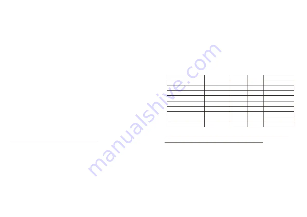
12. Packing List

Name

Specification Quantity

Unit

Application

Screws, Nuts, Flat

Pad

M12*70

2

sets

Fixing the boom

Boom Fixing Bar

1

pcs

Fixing the boom

Cabinet Fixing Bar

2

pcs

Fixing the cabinet

Expansion Screws

M14*150

4

sets

Fixing the cabinet

Support Post

1

pcs

Optional

Radio Emitter

1

pcs

Optional

Keys

2

pcs

For cabinet door

Remote Controller

2

pcs

Manual

1

pcs

Appendix I. Table of Spring Selection and

Suggested Max Speed with Boom Length

This mechanism comes standard with 1 pcs 3.5mm and 1pcs 4.5mm

springs. If the standard springs don't meet the actual boom length

requirement, please replace or add the corresponding spring.

Summary of Contents for S10

Page 1: ...Operating Instructions DC Servo Barrier Gate S10 SFMCU MicroDrive V1 0 ...

Page 2: ... Introduction SUNFRE S10 DC Brushless Servo motorized barrier gate the newly designed maintenance free with exclusive SFMCU MicroDrive unit offers 100 more torque 100 duty are the fastest toll barriers available with an opening time as fast as 0 6 seconds Opening speed is adjustable from 0 6s 0 9s to 6s or more This barrier redefines performance in non stop toll applications It is the ideal soluti...

Page 3: ...cess Reader or Push button or remote controller can be used to trigger the barrier gate to open via a simply dry contact signal After delay timer elapsed barrier gate will close automatically by itself in a certain time optional function 3 8 USER FRIENDLY Motorized arms provide comfortable passage while maintaining a high level and high density of car flow management such as in toll gate 3 10 AUTO...

Page 4: ...nscrew the fastening wing nuts in the bottom of the spring by manual then take off the spring The steps for installation and dis assembly the spring are the opposite 6 2 3 Spring force adjustment When power off adjust the springs balance to make sure the arm will stay in the angle 45 60 degrees towards the horizontal and not going down or going up which mean the spring force is well balanced 7 Cont...

Page 5: ...signal disappeared boom will auto falling to closed 7 1 9 RS485 interface This interface is used for communication between computer and SFMCU control unit We provide SDK for customers to develop software to receive barrier gate status and control barrier gate operations 7 1 10 Battery interface This interface is used for battery the battery can be used to keep barrier gate working normal when powe...

Page 6: ...below items and situations are not included in the range of free service 10 4 1 The user does not follow the instruction and cause any damage of the product 10 4 2 The power supply is not stable over the range of permitted voltage or not accordant to safety electric using standard 10 4 3 The user installs or uses the product in wrong methods cause damage to the appearance of product 10 4 4 Natural...

Page 7: ...ttom port is state 0 Empty is state X The code as below is 10XX0X1X Warning please take out the battery before coding Appendix III Wiring Diagram for R G Light Interface Appendix IV Wiring Diagram for up and down limit output No need Power Boom Length Meter M Spring Diameter Φ mm Suggested max speed Straight Boom Link Hole Selection 2 L 2 5 empty 3 5 0 6 4 L 3 empty 4 5 0 9 4 5 L 4 3 5 4 5 1 2 6 L...

Page 8: ...the speed controlled vice verse Default value is 5 DP07 Max braking strength when closing 0 10 The strength of braking when closing DP08 Default DP10 Opening angle 0 100 Horizontal degree is 0 when power on barrier gate will auto close to find 0position open to position degree is about 90 degrees Sometimes the degrees will more than or less than because of mechanical parts matching or precision is...

Page 9: ...CHAS CHACK SENSOR Sensor check E PL ERROR PULSE Motor Default Phase E CS Gate operation overtime RUNX X is the system operation Mode and the Setting Value of LP02 System Normally Operating dPXX Menu Driven Display NPXX no User Menu Display P H Dates resuming to be Default Value P F Dates resuming Default Value NOPR NO POWER Opening when no power TEST Gate self testing INXX IN NUM xxthe entering ve...

Reviews: