7
•
The Logger1000 supports various communication manners such as WiFi and 4G.
•
The Logger1000 can be connected to various environment sensors, Smart Energy
Meters, Meteo Stations, and inverters in the PV power generation system via an
RS485 bus.
•
Users can access the Web interface via mobile phone or PC, on which parameter
configuration and remote on-line upgrading can be performed.
•
The Logger1000 can transmit data to iSolarCloud and forward background
instructions to downstream devices.
•
The Logger1000 is equipped with grid dispatching function, including active power
control, reactive power regulation, etc.
3.2
Appearance
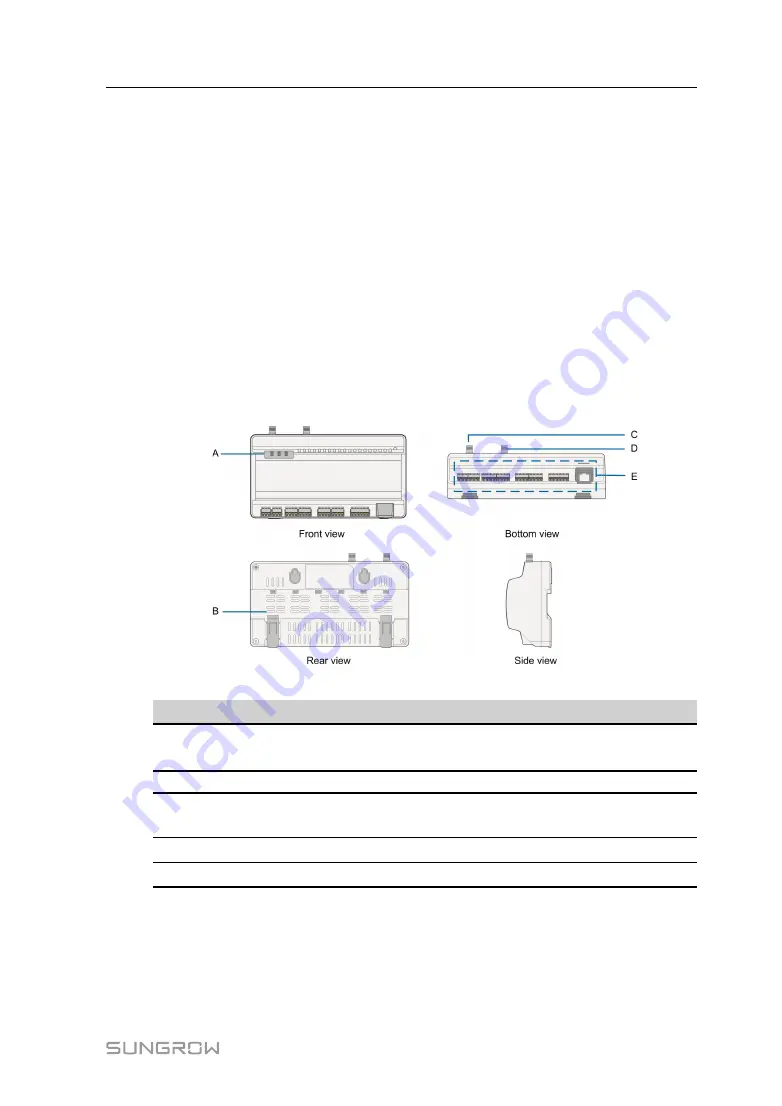
Views of the Logger1000 are shown in the following figure.
F
Fiig
gu
urre
e 3
3--1
1 Appearance
IItte
em
m
D
De
essiig
gn
na
attiio
on
n
D
De
essc
crriip
pttiio
on
n
A
Indicator
Indicate the running state of the
Logger1000
B
Vent
-
C
WLAN antenna mounting
hole
-
D*
4G antenna mounting hole
-
E
Wiring terminal
Refer to
Note: D* is 4G antenna mounting hole. The Logger1000A is provided with the hole while
the Logger1000B is not. Specifically, refer to the actual product received. In the
following, description is given by using the Logger1000A as an example.
User Manual


