23
7.3.1.2 RJ45 port connection
C
Co
om
mm
mu
un
niic
ca
attiio
on
n c
ca
ab
blle
e ssp
pe
ec
ciiffiic
ca
attiio
on
n::
C
Ca
ab
blle
e
T
Tyyp
pe
e
RS485 communication cable
Shielded twisted pair Ethernet cable
C
Ca
ab
blle
e c
co
on
nn
ne
ec
cttiio
on
n p
prro
oc
ce
ed
du
urre
e::
Step 1
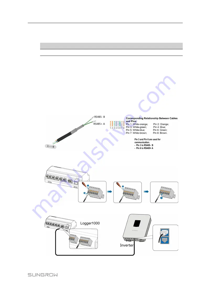
Lead the RS485 communication cable from the inverter to the wiring area of
Logger1000.
Step 2
Strip the insulation layer of the communication cable with an Ethernet wire stripper, and
lead the corresponding RS485A/B signal cables out. Insert cord end terminals into
signal cable RS485+ A and signal cable RS485- B, and crimp them with a crimper. Cut
off the redundant signal cable and warp it with a heat-shrink tubing.
If the communication cable is Shielded Ethernet cable, white-green wire 3 is defined as
RS485- B wire and the green wire 6 as RS485+ A wire.
Step 3
Connect the communication cable to the RS485 ports of the Logger1000, as shown in
the figure below.
Step 4
Connect the Logger1000 to the inverter.
-- -- E
En
nd
d
User Manual


