24
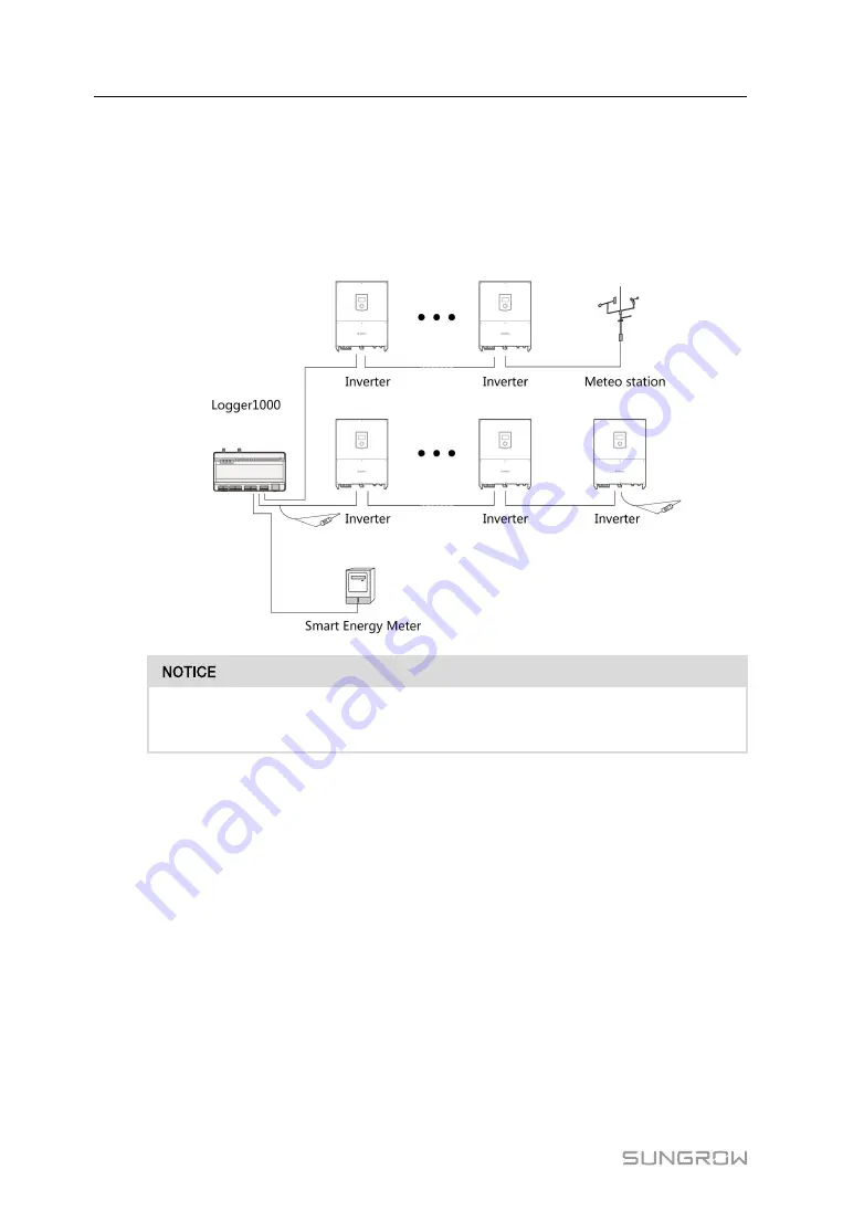
7.3.2 Connection to multiple devices
Multiple inverters are connected to the Logger1000 in the RS485 daisy chain manner. If
more than 15 inverters (14 inverters, for devices other than Logger1000) are connected
on the RS485 bus, it is recommended to connect a 120Ω terminal resistor in parallel on
the RS485A and RS485B lines at the head and tail end of the bus.
With an outdoor device connected to the Logger1000, it is recommended to
connect an SPD to protect the Logger1000 from lightning damage.
•
The Logger1000 allows for 3 inputs of RS485 buses and 30 devices at most.
•
When the number of device types is less than or equal to the number of RS485 ports
of Logger1000, it is recommended to connect different types of devices to different
RS485 ports separately.
•
The addresses of devices on each RS485 bus must be different from one another
and within the address range set for the Logger1000 (address range of residential
inverters and string inverters manufactured by SUNGROW: 1-247; address range of
third-party devices: 1-255). Otherwise, communication error will occur.
•
Serial port parameters of each device on the RS485 bus should be consistent with
those of the Logger1000. The serial port parameters include baud rate, data bit, stop
bit, and check bit.
7.3.3 Connection to Smart Energy Meter
It is recommended to use the Smart Energy Meter whose communication protocol
complies with DL/T645-1997/2007 protocol or Modbus protocol. Logger1000 can be
User Manual


