44
Step 3
Select the port (COM1/COM2/COM3/NET) that the meter is actually connected to in the
“Port”.
Step 4
Select “Others” option in the “Device Model”.
Step 5
Select “Custom” option in the “Configuration Method”. Click “Next” to enter
“Configure Measuring Point” the interface.
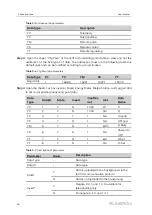
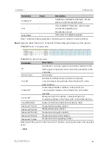
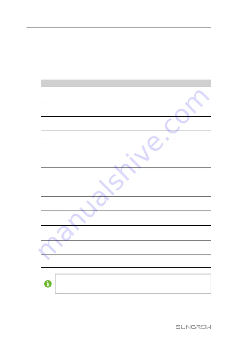
Table 9-1
Parameter description
P
Pa
arra
am
me
ette
err
D
De
essc
crriip
pttiio
on
n
Byte Order
Refer to the communication protocol of the meter,
parse the order of the read byte stream
PT Transformation Ratio
Refer to the communication protocol of the meter,
voltage transformation ratio
CT Transformation Ratio
Refer to the communication protocol of the meter,
current transformation ratio
Beginning Address
The beginning address of the device
Quantity of Device
The number of the meter
Debug Address
The device address to be read when click “Read-
Back”, the range is [(“Beginning Address”), (“-
Beginning Address” + ”Quantity of Device”-1)]
Modbus Address
Refer to the communication protocol of the meter, the
address of Modbus communication protocol, priority to
select the register address corresponding to the data
type of “Float”
Register Type
Refer to the communication protocol of the meter, the
register type of the corresponding measuring point
Data Type
Refer to the communication protocol of the meter, the
data type of the corresponding measuring point
Read Type
With or without framing when send messages at this
point, recommend to choose continuous type
Coefficient
Refer to the communication protocol of the meter, the
coefficient that multiplied the value of the data read
Read-back Value
The value of the selected measuring point read when
clicking "Read-back”
The user can select up to 21 objects for setting. Their corresponding
parameters such as Modbus address please refer to the user manual of the
connected meter.
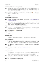
Step 6
Select the points to be measured, click “Read-back” to read the information from the
meter in real time to check the correctness of parameter setting.
User Manual


