9
4
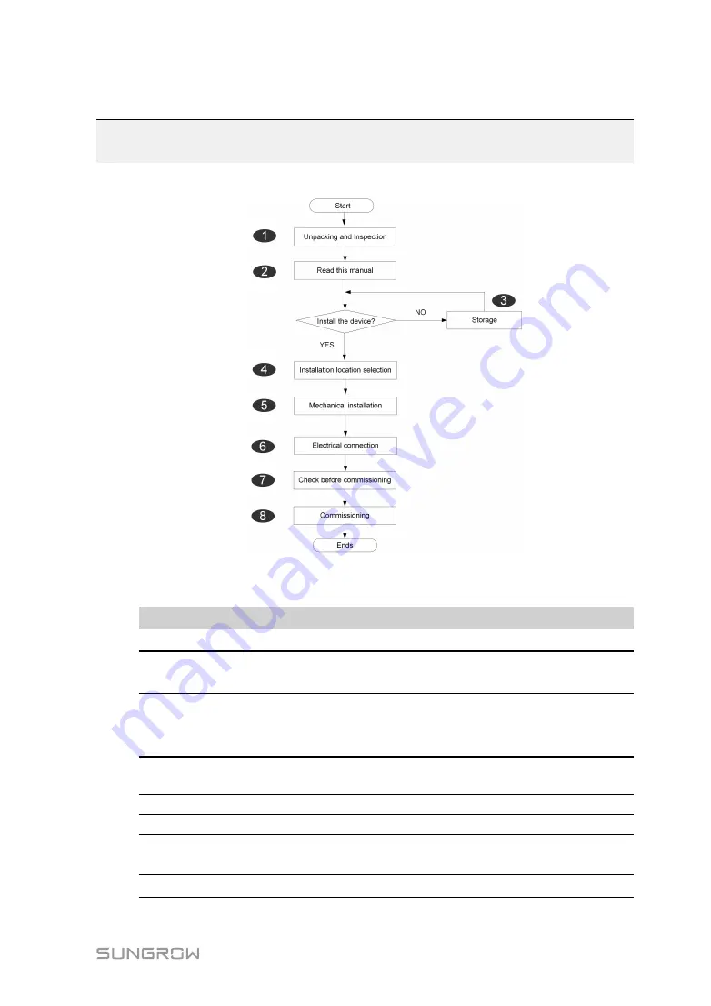
Installation Flow
The following figure shows the overall installation flow of Logger1000.
F
Fiig
gu
urre
e 4
4--1
1 Installation Flow
Table 4-1
Description of the installation flow
N
No
o..
P
Prro
oc
ce
ed
du
urre
e
R
Re
effe
erre
en
nc
ce
e c
ch
ha
ap
ptte
err
1
Unpacking and inspection
2
Read this user manual,especially
“Safety Instructions”
3
Store the Logger1000 properly if
it is not to be installed
immediately
4
Installation location selection
5
Mechanical installation
6
Electrical connection
7
Check before commissioning
8
Commissioning


