28
Step 2
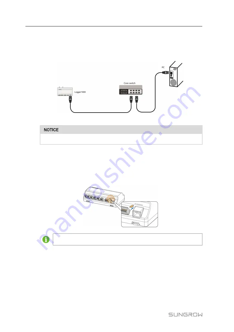
Insert one end of the cable into the port of the Ethernet switch and the other end to the
"ETH" port of the Logger1000.
Step 3
Set IP address of the ETH port to be within the same network segment as that of the
background monitoring system.
F
Fiig
gu
urre
e 7
7--2
2 Connection to PV background system
Default IP of the "ETH": IP12.12.12.12.
-- -- E
En
nd
d
7.5
Connection to Micro-SIM
Micro-SIM card size: 12mmx15mm.
Support of hot plug of Micro-SIM.
7.6
Connection to Power Box
The Logger1000 supports DC24V power supply. Prepare two-core DC cable, three-
core AC cable, and grounding cable before wiring. Power cable specifications are
shown in the table below.
User Manual


