22
P
Po
orrtt
F
Fu
un
nc
cttiio
on
n
D
De
essc
crriip
pttiio
on
n
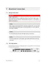
ETH1, ETH2
Ethernet port
Can be connected to the
background through devices like
switch and router.
DIN
Digital input
Dry contact input interface
USB-HOST
USB port
Reserved
SD
SD port
Reserved
Debug
Debug port
Used for debugging of the
Logger3000
RST
Reset
Used for hardware reset of
Logger3000
DO1~DO4
Digital output
Relay output interface
Relay specification: 250Vac/1A or
30Vdc/1A
PT1, PT2, AI1~AI4
Analog input
PT1、PT2 detect range:-30℃
~120℃
AI1~AI2:4~20mA/0~10Vdc
AI3~AI4:0~0.1Vdc
A1B1~A6B6
RS485 communication
interface
Support of 6 inputs of RS485
Can be connected to both slave
device and background
CAN
CAN communication
port
Reserved
24V
DC24V power supply
port
If the current is ≤2.0A, the switch
mode power supply at this port
requires reinforced insulation.
AC(100~277V)
AC power supply port
Connecting 100~277Vac (50/
60Hz), current≤0.5A
GPS/BDS
GPS antenna interface
Used for time synchronization and
positioning
RF
Wireless antenna
interface
Reserved
Grounding hole
Connecting protective grounding
cable
PLC(L1, L2)
PLC communication
interface
Can be connected to string
inverters equipped with PLC
communication function
User Manual
Summary of Contents for Logger3000
Page 2: ......
Page 6: ......
Page 14: ...8 f fiig gu ur re e 3 3 2 2 Star networking 3 Product Introduction User Manual...


