24
C
Co
on
nn
ne
ec
cttiin
ng
g tto
o M
Mu
ullttiip
plle
e IIn
nvve
errtte
errss
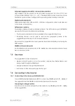
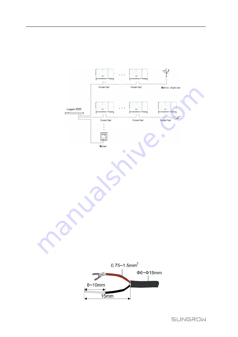
Multiple inverters are connected to the Logger3000 in the RS485 daisy chain manner. If
more than 15 inverters are connected on the RS485 bus, it is recommended to connect
a 120Ω terminal resistor in parallel on the RS485A and RS485B lines at the head or tail
end of the bus.
•
The Logger3000 supports 6 RS485 buses and 200 devices at most. Each RS485
bus supports 60 devices at most.
•
Devices of different types must be connected to different RS485 communication
ports of the Logger3000. For example, the transformer and the inverter should be
connected to different RS485 communication ports of the Logger3000.
•
The address of each device on the RS485 bus should be within the set address
range (1 to 246) of the Logger3000 without repetition. Otherwise, communication
failure occurs.
•
Serial port parameters of each device on the RS485 bus should be consistent with
those of the Logger3000. The serial port parameters include baud rate, data bit, stop
bit, and check bit.
C
Co
on
nn
ne
ec
cttiio
on
n P
Prro
oc
ce
ed
du
urre
e
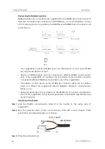
step 1
Lead the RS485 communication cable from the inverter to the wiring area of
Logger3000.
step 2
Strip the protection layer of the communication cable with a wire stripper. Cable
specification and stripped length are as follows:
step 3
Crimp the wiring terminal.
User Manual
Summary of Contents for Logger3000
Page 2: ......
Page 6: ......
Page 14: ...8 f fiig gu ur re e 3 3 2 2 Star networking 3 Product Introduction User Manual...


