26
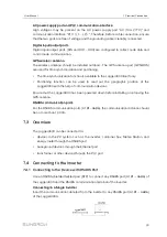
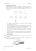
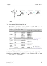
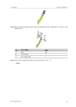
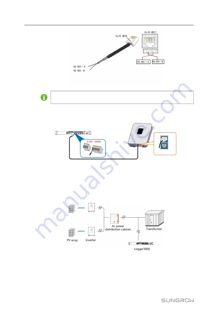
The white-green wire 3 is defined as RS485- B wire and the green wire 6 as
RS485+ A wire.
step 3
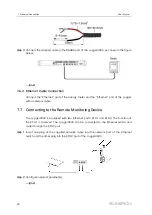
Connect the communication cable to the RS485 port of the Logger3000, as shown in
the figure below.
-- -- E
En
nd
d
7.4.3 Connecting to the Inverter with PLC Port
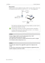
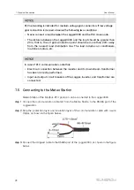
Integrated with PLC master node, the Logger3000 can be connected to the inverter
integrated with PLC slave node and achieve PLC communication by using existing
power cable.
P
Prre
ep
pa
arra
attiio
on
n b
be
effo
orre
e w
wiirriin
ng
g
•
Disconnect the transformer from the grid.
•
Disconnect the DC side of the inverter and make sure the system is in safe state.
User Manual
Summary of Contents for Logger3000
Page 2: ......
Page 6: ......
Page 14: ...8 f fiig gu ur re e 3 3 2 2 Star networking 3 Product Introduction User Manual...


