26
R
RS
S4
48
85
5 c
co
om
mm
mu
un
niic
ca
attiio
on
n p
po
orrttss
For the RS485 communication ports (A1B1~A7B7), the communication distance should
be no more than 1,000m.
7.3
Overview
The Logger4000 can be connected to:
•
devices in the PV system such as the inverter, combiner box, Meteo Station, and
energy meter through the RS485 port
•
background devices through the Ethernet port
•
transformer or other devices through the MPLC port
7.4
Connecting to the Inverter
7.4.1 Connecting to the Device with RS485 Port
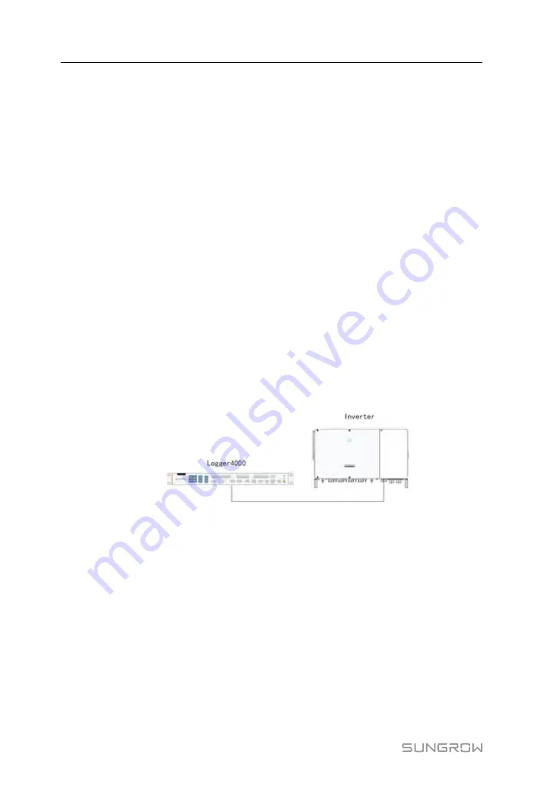
Use an RS485 shielded twisted pair (STP) to connect any RS485 port (A1B1–A7B7) of
the Logger4000 and the RS485 communication terminal of the inverter.
C
Co
on
nn
ne
ec
cttiin
ng
g tto
o a
a S
Siin
ng
glle
e IIn
nvve
errtte
err
Insert the communication cable led from the inverter to any RS485 port (A1B1–A7B7)
of the Logger4000.
C
Co
on
nn
ne
ec
cttiin
ng
g tto
o M
Mu
ullttiip
plle
e IIn
nvve
errtte
errss
Multiple inverters are connected to the Logger4000 in the RS485 daisy chain manner. If
more than 15 inverters are connected on the RS485 bus, it is recommended to connect
a 120Ω terminal resistor in parallel on the RS485A and RS485B lines at the head or tail
end of the bus.
User Manual


