28
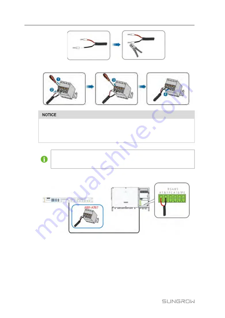
step 4
Crimp the wiring terminal.
•
RS485A is connected to port A while RS485B is connected to port B.
•
The RS485 communication cable must be the shielded twisted pair with the
shielding layer single-point grounded.
When a multi-core and multi-strand copper core cable is used, the
communications cable connected to an RS485 port on Logger must be press-
fitted to cord end terminals of proper specification.
step 5
Connect the wiring terminal to the terminal "A1B1~A7B7" of the Logger4000.
-- -- E
En
nd
d
7.4.2 Connecting to the Inverter with MPLC Port
Integrated with MPLC master node, the Logger4000 can be connected to the inverter
integrated with MPLC slave node and achieve MPLC communication by using existing
power cable.
User Manual


