31
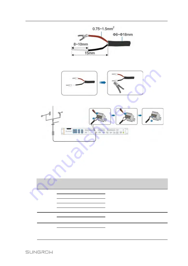
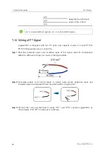
step 3
Assemble proper cord end terminals to communication cable whose protective layer
and insulation layer are stripped off and crimp them with a crimping tool.
step 4
Connect the cable to the RS485 port of the Logger4000, as shown in the figure below.
-- -- E
En
nd
d
7.6
Connecting to the Energy Meter
The Logger can be connected to the energy meter through the RS485 port or the
Ethernet port. Specifically, refer to the table below.
E
En
ne
errg
gyy
M
Me
ette
err
C
Co
om
mm
mu
un
niic
ca
att--
iio
on
n P
Po
orrtt
P
Po
orrtt
D
De
effiin
niittiio
on
n
P
Prro
otto
oc
co
oll
T
Tyyp
pe
e
W
Wiirriin
ng
g M
Me
etth
ho
od
d
Wasion
24
RS485-A
Modbus
RTU
25
RS485-B
26
Public
27
RS485-A
28
RS485-B
Acrel
21
RS485-A
Modbus
RTU
22
RS485-B
Weidmull-
er
EM610
17
RS485-A
Modbus
RTU
16
RS485-B
User Manual


