System Manual
32
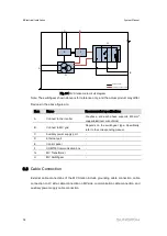
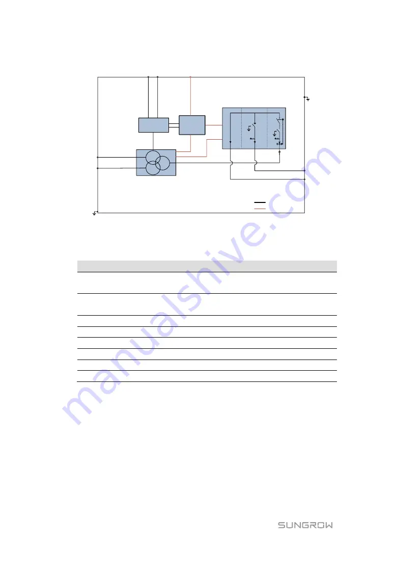
Power cable
A
F
Communication cable
H
G
B
D
C
E
Fig. 6-1
MV Station main circuit diagram
Note: The switchgear shown above is for reference only, and the actual product may differ.
Devices in the above figure are:
Item
Name
Recommended specifications
A
Connect to the inverter
Six-phase, and each phase supports 400 mm
2
copper/aluminum wire utmost
B
Connect to MV grid
Depends on the switchgear type. Specifically,
refer to the corresponding manual.
C
Auxiliary power supply port
-
D
Ethernet port
-
E
Control panel
-
F
COM100 Communication box
-
G
MV Transformer
-
H
MV Switchgear
-
6.3
Cable Connection
External cable connections of the MV Station include grounding cable connection, cable
connection on LV side, cable connection on MV side, communication cable connection, and
auxiliary power supply cable connection.
Summary of Contents for MVS6250
Page 2: ......


