User Manual
8
D (170)
W (457)
H
(515
)
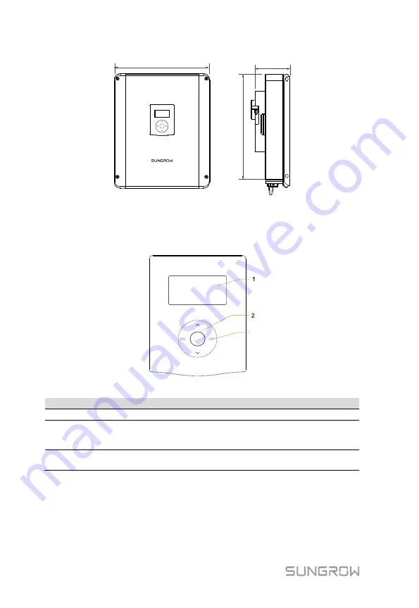
Fig. 2-2
Dimensions (unit: mm)
LCD Panel
The LCD panel with an indicator and four buttons is on the front of the inverter.
3
Fig. 2-3
LCD Panel
No.
Name
Description
1
Screen
To display the information.
2
Indicator
Green and red can be indicated via the indicator, from
which user can know the current status. For detailed
definition, see
3
Buttons
User can operate the LCD menu via the four buttons.
For detailed functions, see
2.1.2 Energy Meter
The Energy Meter is installed next to the main switch to detect the electrical
measured values at the grid-connected point. It communicates with the inverter
via an RS485 connection. The dimensions are shown below.


