User Manual
55
For the installation and the cable connection of STB5K-20, see the
Quick Installation Guide delivered with the STB5K-20 module.
6.9.1 Connecting the Power Cables
Risk of inverter damage due to incorrect cable connection. Do not
connect the grid power wires to LOAD terminals.
A residual current device (RCD) of 30 mA (type B) should be installed
on the output side of the LOAD port of the backup box STB5K-20.
The neutral lines for the grid, the EPS and the inverter AC terminals are all
inter-connected inside the STB5K-20. And it is the same for the PE lines.
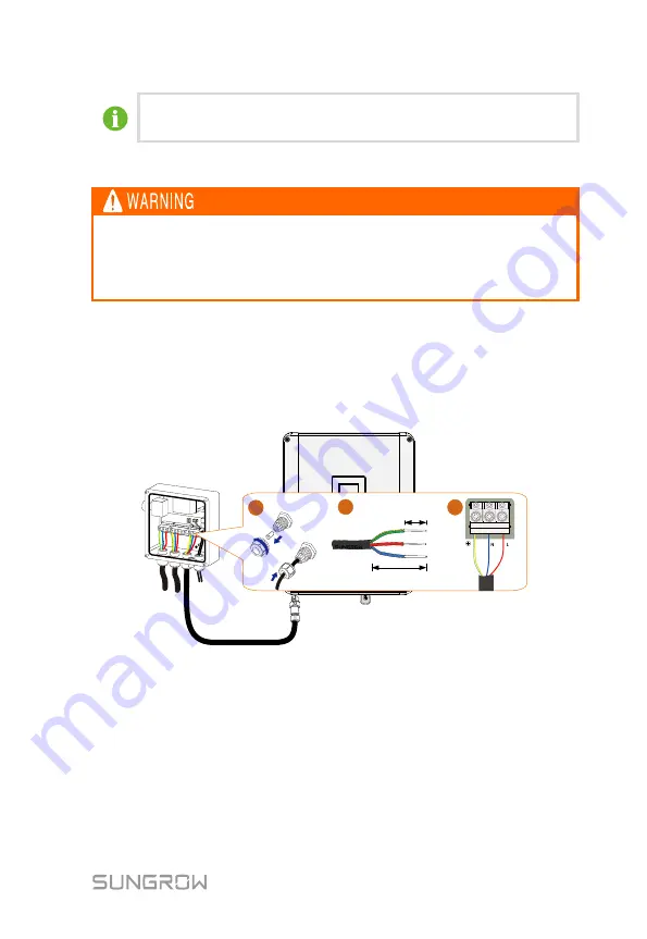
Connect terminals L1, N1 and PE to the grid, and connect terminals L4, N4 and
PE to the AC connector and then to the AC terminal on the SH5K-20.
Cross-section: 4 mm
²
, cable diameter: 11 mm–14 mm
Grid
EPS
Load
SH5K-20 AC
3
PE
L
N
10 mm-15 mm
40 mm-50 mm
1
2
6.9.2 Connecting the Control Cable and DI Cable
The control cable (with end marks
C1
and
C2)
and the DI cable (with end marks
DI1
,
DI2
,
DI3
and
VDD)
are equipped in the backup box STB5K-20 before
delivery.


