User Manual
96
Parameter
Explanation
Default
Range
V3 Ref.
Grid voltage
reference value 3
250.0 V
244.0 V
V4 Ref.
Grid voltage
reference value 4
265.0 V
255.0 V
P1 Ref.
Active power at
voltage V1
100.0 %
100.0 %
000.0 %–100.0 %
P2 Ref.
Active power at
voltage V2
100.0 %
100.0 %
P3 Ref.
Active power at
voltage V3
100.0 %
100.0 %
P4 Ref.
Active power at
voltage V4
020.0 %
020.0 %
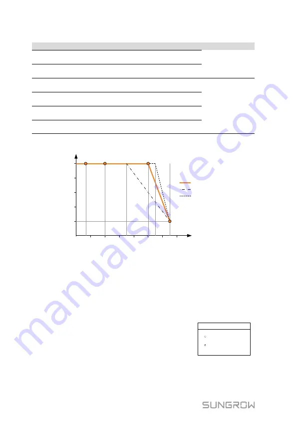
The response curve is defined by the voltage reference values and
corresponding power levels.
Power
,
P
/P
rated
%
200
Inverter Voltage, V
V2
V3
V4
210
220
230
240
250
260
270
40%
60%
20%
80%
0%
V1
100%
Default characteristic
Range (lower limit)
Range (upper limit)
Fig. 12-3
Volt-Watt Response Curve (“AU” for example)
12.3.2 Volt-watt Response for Battery Charging
When the power from the grid is required to charge the energy storage system,
the import power from the grid varies in response to the grid voltages. The
response curve is defined by the voltage reference values and the
corresponding power consumption from the grid for charging energy storage.
The Volt-watt response mode for battery charging
is enabled by default.
Set four grid voltages and the corresponding
power consumption upper limits (in % to the
maximum input power 3000 W).
Volt-watt (Chrg)
Enable
Disable
1/2


