background image

SAFETY INFORMATION


DANGER


DANGER


• EXPLOSION - FIRE HAZARD 
• Keep solid combustibles, such as building materials, 
paper or cardboard, a safe distance away from the 
heater as recommended by the instructions. 
• Provide adequate clearances around air openings 
into the combustion chamber. 
• Never use the heater in spaces which do or may 
contain volatile or airborne combustibles, or products 
such as gasoline, solvents, paint thinner, dust particles 
or unknown chemicals. 
• During operation, this product can be a source of 
ignition. Keep heater area clear and free from 
combustible materials, gasoline, paint thinner, cleaning 
solvents and other flammable vapors and liquids. Do 
not use heater in areas with high dust content. 
Minimum heater clearances from combustible 
materials: 36" (91 cm) from the sides & 24" (61 cm) 
from the top. 


DANGER


• EXPLOSION - FIRE HAZARD 
• Never store propane near high heat, open flames, 
pilot lights, direct sunlight, other ignition sources or 
where temperatures exceed 120 degrees F (49°C). 
• Propane vapors are heavier than air and can 
accumulate in low places. If you smell gas, leave the 
area immediately. 
• Never install or remove propane cylinder while heater 
is lit, near flame, pilot light or other ignition sources or 
while heater is hot to touch. 
• This heater is red hot during use and can ignite 
flammables too close to the burner. Keep flammables 
at least 36" (91 cm) from sides & 24" (61 cm) from top. 
Keep gasoline and other flammable liquids and vapors 
well away from heater. 
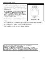
• Store the propane cylinder outdoors in a well ventilated 
space out of reach of children. Never store the propane 
cylinder in an enclosed area (house, garage, etc.). If 
heater is to be stored indoors, disconnect the propane 
cylinder for outdoor storage. 

• CARBON MONOXIDE HAZARD 
• This heater is a combustion appliance. All 
combustion appliances produce carbon monoxide 
(CO) during the combustion process. This product is 
designed to produce extremely minute, non-hazardous 
amounts of CO if used and maintained in accordance 
with all warnings and instructions. Do not block air 
flow into or out of the heater. 
• Carbon Monoxide (CO) poisoning produces flu-like 
symptoms, watery eyes, headaches, dizziness, fatigue 
and possibly death. You can't see it and you can't 
smell it. It's an invisible killer. If these symptoms are 
present during operation of this product, get fresh air 
immediately! 
• For outdoor use only. 
• Never use inside house, or other unventilated or 
enclosed areas. 
• This heater consumes air (oxygen). Do not use in 
unventilated or enclosed areas to avoid endangering 
your life. 


CAUTION


SERVICE SAFETY 

• Keep all connections and fittings clean. Make sure 
propane cylinder valve outlet is clean. 
• During set up, check all connections and fittings for 
leaks using soapy water. Never use a flame. 
• Use as a heating appliance only. Never alter in any 
way or use with any device. 


CAUTION


CAUTION indicates an imminently hazardous situation 
which, if not avoided, may result in minor or moderate 
personal injury, or property damage. 


CAUTION


An appliance may be installed with shelter no more 
inclusive than: 
(a) With walls on all sides, but with no overhead cover. 
(b) Within a partial enclosure which includes an overhead 
cover and no more than two side walls. These side walls 
may be parallel, as in a breezeway, or at right angles to 
each other. 
(c) Within partial enclosure which includes an overhead 
cover and three side walls, as long as 30 percent or 
more of the horizontal periphery of the enclosure is 
permanently open. 

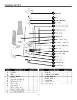
Summary of Contents for PHTR-LED

Page 1: ...NING Do not store or use gasoline or other flammable vapors and liquids in the vicinity of this or any other appliance An LP cylinder not connected for use shall not be stored in the vicinity of this or any other appliance WARNING For Outdoor Use Only WARNING Improper installation adjustment alteration service or maintenance can cause property damage injury or death Read the installation operation...

Page 2: ...mbly O Bottom plate P Front Panel Q Ceramic Fiber R Led controller PART DESCRIPTION QUANTITY PART DESCRIPTION QUANTITY A Reflector 1 L Block Belt 1 B Mesh 1 M Gas Hose Regulator 1 C Glass Tube Fixer 1 N Wheel Assembly 2 D Top Plate 1 O Bottom plate 1 E Upper Support Long 3 P Front Panel 1 F Protective Guard 3 Q Ceramic Fiber 1 G Glass Tube 1 R Led controller 1 H Side Panel 2 I Black Silicone Ring ...

Page 3: ...f this product This manual should be read in conjunction with the labeling on the product Safety precautions are essential when any mechanical or propane fueled equipment is involved These precautions are necessary when using storing and servicing this patio heater Using this equipment with the respect and caution demanded will reduce the possibilities of personal injury or property damage The fol...

Page 4: ...tc If heater is to be stored indoors disconnect the propane cylinder for outdoor storage CARBON MONOXIDE HAZARD This heater is a combustion appliance All combustion appliances produce carbon monoxide CO during the combustion process This product is designed to produce extremely minute non hazardous amounts of CO if used and maintained in accordance with all warnings and instructions Do not block a...

Page 5: ...e questions about heater use Other standards govern the use of fuel gases and heat producing products for specific uses Your local authorities can advise you about these In Canada installation must conform to local codes If no local codes exist follow the current National standards of CANADA CAN CGA B 149 2 Alert children and adults to the hazards of high surface temperatures Stay away from these ...

Page 6: ...ower supports K Insert the hoods of control box assembly J to the upper holes of the three lower J support K Note Make sure align the side of bottom plate O with the holes with the side of control box assembly J with the magnet K O 2 Insert three upper supports E to the three 2 lower supports K E ...

Page 7: ...nd the bottom plate O with M5 x 12 mm screws DD DD Hardware Used DD M5 x 12 mm Screw x 9 LL Phillips x 1 Screwdriver 4 Use Phillips screwdriver LL to secure 4 the top plate D to the upper supports E with M5 x 12 mm screws DD DD D Hardware Used DD M5 x 12 mm Screw x 6 LL Phillips x 1 Screwdriver ...

Page 8: ...he bottom plate O with M6 x 12 mm bolts EE Hardware Used EE M6 x 12 mm Bolt x 8 O EE KK Wrench x 1 N 6 Use Phillips screwdriver LL to secure 6 the block belt L to the lower supports K with M5 x 12 mm screws DD L Hardware Used DD DD M5 x 12 mm Screw x 2 K LL Phillips x 1 Screwdriver ...

Page 9: ...ps of the control box assembly J G J 8 Assembly the glass tube fixer C 8 Insert the ceramic fiber Q to the quartz tube Q fixer Press the glass tube fixer to the glass tube Make sure the ceramic fiber is outside of glass tube Use Phillips screwdriver LL to secure the glass tube fixer C to the top plate D with M5 x 12 mm screws DD C Hardware Used DD M5 x 12 mm Screw X 3 DD Phillips X 1 Screwdriver L...

Page 10: ...x 12 DD LL Phillips x 1 H Screwdriver 10 Assemble the chain II and wafer MM 10 to the inside of front panel with M4x10 screw HH and then install the knob GG to M4x10 screw Hang the chain to the hole on the control box assembly J and put the pothook of front panel to the holes of bottom plate J Hardware Used HH GG Knob x 1 MM GG HH Screw M4 X 10 x 1 II II Chain x 1 P MM wafer x 1 LL Philips x 1 scr...

Page 11: ...he mesh B and protective guard F to the top DD plate D with M5 x 12 mm screws DD and fixing bracket FF Hardware Used DD M5 x 12 mm Screw x 3 FF Fixing Bracket x 3 Phillips LL Screwdriver x 1 12 Carefully lean the assembly and attach 12 AA reflector A to mesh B with studs CC A small flat washers BB on either side of reflector A and then wing nuts AA BB Gently return the assembly to the upright CC p...

Page 12: ...connected and removed from the appliance A cylinder must be stored outdoors in a well ventilated area out of the reach of children A disconnected cylinder must have dust caps tightly installed and must not be stored in a building garage or any other enclosed area The maximum inlet gas supply pressure 250 PSI The minimum inlet gas supply pressure 5 PSI is required for purpose of input adjustment Th...

Page 13: ...tion of block chip like figure a 14 2 Adjust the position of block chip like figure b Pull out the LED belt box 14 3 When changing the batteries first take out the LED belt box and then battery box after that open the battery box and change the batteries like figure c Figure a Figure b Figure c ...

Page 14: ...ic yellow Static light blue Static pink 7color fade change Static straw yellow Static sky blue Static purple 3 base color jumpy 3 Panel specification and connecting drawing as follows POWER DC12V 4 Warning Supply voltage of this product is DC12V never connect to DC24V or AC220V Never connect two wires directly in case of short circuit Lead wire should be connected correctly according to colors tha...

Page 15: ...A B339 The cylinder must have a listed overfilling prevention device Standard 20 lb tank The cylinder must have a connection device compatible with the connection for the appliance The cylinder used must include a collar to protect the cylinder valve Never connect an unregulated propane cylinder to the heater Do not store a spare LP gas cylinder under or near this appliance Never fill the cylinder...

Page 16: ...ll patio heater and light valves are OFF 5 Turn cylinder valve ON If bubbles appear at any connection there is a leak 1 Turn cylinder valve OFF 2 If leak is at hose regulator connection Add Teflon tape and re attach the regulator to the hose with wrenches If bubbles continue appearing the hose should be returned to the place of purchase 3 If leak is at regulator cylinder valve connection disconnec...

Page 17: ...the cylinder cover is clear of debris Be sure any component removed during assembly or servicing is replaced and fastened prior to starting Before Lighting 1 Heater should be thoroughly inspected before each use and by a qualified service person at least annually If relighting a hot heater always wait at least 5 minutes 2 Inspect the hose assembly for evidence of excessive abrasion cuts or wear Su...

Page 18: ...es should be allowed before attempting to light WARNING If you attempt to relight the pilot without waiting you will get a flash that could cause bodily harm and property damage If you experience any ignition problem please consult Troubleshooting on page 21 Caution Avoid inhaling fumes emitted from the heater s first use Smoke and odors from the burning of oils used in manufacturing will appear B...

Page 19: ...h or move the heater until it is completely cooled approx 45 minutes Shut Down 1 Turn control knob clockwise to PILOT Normally burner will make a slight popping sound when extinguished Burner will extinguish but PILOT will remain ON 2 To extinguish PILOT depress control knob and continue to turn it clockwise to OFF 3 Turn cylinder valve clockwise to OFF and disconnect regulator when heater is not ...

Page 20: ...uent cleaning may be required as necessary It is imperative that control compartment burner and circulating air passageways of the heater be kept clean After Operation 1 Gas control is in OFF position 2 Gas tank valve is OFF 3 Disconnect propane gas cylinder CARE AND MAINTENANCE WARNING FOR YOUR SAFETY Do NOT touch or move heater for at least 45 minutes after use Reflector is hot to touch Allow re...

Page 21: ... Replace anti tilt switch Connect wire properly Burner won t light Propane cylinder is frosted over Wait until the propane cylinder warms up and becomes unfrosted Blockage in orifice Clear blockage Control knob is not in ON position Turn control knob to ON Burner flame is low Gas pressure is low Turn cylinder valve OFF and replace cylinder Outdoor temperature is less than 40ºF and tank is less tha...

Page 22: ...mitter screen or domes Storage Between uses Turn control knob OFF Disconnect LP cylinder Store heater upright in an area sheltered from direct contact with inclement weather such as rain sleet hail snow dust and debris If desired cover heater to protect exterior surfaces and to help prevent build up in air passages Note Wait until heater is completely cooled off before covering During periods of e...

Page 23: ...ssembly O Bottom plate P Front Panel Q Ceramic Fiber R Led controller PART DESCRIPTION QUANTITY PART DESCRIPTION QUANTITY A Reflector 1 L Block Belt 1 B Mesh 1 M Gas Hose Regulator 1 C Glass Tube Fixer 1 N Wheel Assembly 2 D Top Plate 1 O Bottom plate 1 E Upper Support Long 3 P Front Panel 1 F Protective Guard 3 Q Ceramic Fiber 1 G Glass Tube 1 R Led controller 1 H Side Panel 2 I Black Silicone Ri...

Page 24: ...24 ...

Page 25: ...zes any person or entity to assume for it any obligation or liability associated with its products Customer will be responsible for any expense for delivery to and from the authorized SUNHEAT International servicing dealer A copy of the original receipt must accompany all warranty claims WARRANTY CARD SUNHEAT INTERNATIONAL 3724 ARCH AVE GRAND ISLAND NE 68803 877 467 8643 TO REGISTER YOUR WARRANTY ...

Reviews: