background image

Maint Storage

1.  Before operating, grease or oil wheel bearings, use 

automotive bearing grease or heavy weight oil.

2.  Periodically tighten all screws to make sure everything is 

secured before operating.

3.  Before operating make sure the tire pressure is within  

15 – 20 PSI.

4.  After each use, clean the cart thoroughly.
5.  Annually, apply a light coat of varnish to all wood surfaces.
6.  Use a glossy black enamel spray paint to touch up 

scratched or worn painted metal surfaces.

7.  Never exceed load capacity rating of 300 lbs (136 kg). It 

will damage the cart. 

8.  Store indoors during severe weather and winter months. 

NOTE: If a part needs replacement, only use parts that meet 

the manufacturer’s specifications. Replacement parts that do 

not meet specifications may result in a safety hazard or poor 

performance.

S Support

If your Sun Joe

®

 SJGC7 garden cart requires service or 

maintenance, please call Snow Joe

®

 + Sun Joe

®

 customer 

service at 1-866-SNOWJOE (1-866-766-9563) for assistance.

Model + Serial Numbers 

When contacting the company or arranging service from an 

authorized dealer, you will need to provide the model and serial 

numbers, which can be found on the decal located on the cart. 

Copy these numbers into the space provided below.

8

EN

Record the following numbers from the housing or handle of your  

new product:

Model #:

Serial #:

S   J    G  C    7 

Summary of Contents for SJGC7

Page 1: ...au 1 866 SNOWJOE 1 866 766 9563 2018 by Snow Joe LLC All rights reserved Original instructions SAVE THESE INSTRUCTIONS 2018 by Snow Joe LLC Derechos reservados Instrucciones originales GUARDE ESTAS INSTRUCCIONES 2018 by Snow Joe LLC Tous droits réservés Instructions d origine CONSERVER CES INSTRUCTIONS Model Modelo Modèle SJGC7 SJ SJGC7 880E S F MR3 7 CUBIC FOOT HEAVY DUTY GARDEN UTILITY CART Carr...

Page 2: ...cals known to the state of California to cause cancer birth defects or other reproductive harm 1 Do not at any time carry passengers sitting or standing in the cart 2 Do not allow children to play on stand upon or climb in the cart 3 Always inspect the cart before using to assure the cart is in good working condition 4 Replace or repair damaged or worn parts immediately 5 Always check and tighten ...

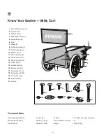
Page 3: ... M6 x 50 screw 8 12 M6 x 30 screw 4 13 M6 x 25 screw 15 14 Cotter pin 4 15 Handle knob 8 16 M6 hex nuts 19 17 Flat washer 1 4 18 Flat washer 2 50 19 Lock washer 4 20 Axle clamp 2 21 Wrench Technical Data Heaping Load Capacity 7 cubic foot Max Weight Capacity 300 lbs 136 kg Cart material Plywood steel Wheels 20 in 50 8 cm bicycle wheels Removable Front Panel Yes Weight 55 lbs 25 kg 3 EN 11 12 13 14...

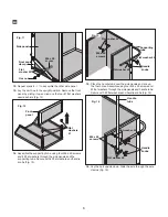
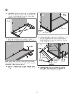
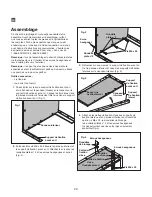
Page 4: ...ngle clamp Fig 1 2 Push three M6 x 25 screws through the bottom panel and the front angle clamp Secure the screws with 2 flat washers and hex nuts and tighten Fig 2 3 Turn the front angle clamp and bottom panel upside down and lay the side angle clamps on the bottom panel Fig 3 4 Secure the axle clamps to the side angle clamps and the bottom panel by using four M6 x 30 screws lock washers 2 flat w...

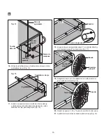
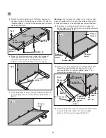
Page 5: ...upporting strap on the side angle clamp and the front angle clamp by two M6 x 25 screws four 2 flat washers and 2 hex nuts Fig 9 10 Secure the side panel with the side angle clamp by a M6 x 25 screw two 2 flat washers and a hex nut Fig 10 11 Secure the side panel with the front angle clamp by a M6 x 25 screw two 2 flat washers and a hex nut Fig 11 Fig 6 Flat washers 1 Fig 7 Front panel Fig 8 Side ...

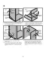
Page 6: ... 15 Place the handle tube over the side panels and line up the four holes Assemble using four M6 x 50 screws and 2 flat washers through the side panels and handle tube Secure with 2 flat washers and handle knobs Fig 14 16 Lay the cart upside down Slide the axle through the axle clamps Fig 15 Fig 11 Side panel Front angle clamp M6 x 25 screw Flat washer 2 Hex nut Fig 12 Front panel Flat washers 1 F...

Page 7: ... the wheel with another cotter pin on the outer hole at the end of the axle Fig 18 20 Repeat steps 17 19 to assemble the other wheel 21 Tighten the two nuts on the axle clamps on both sides Fig 18 22 Turn cart right side up so the cart rests on its wheels Slide the front panel in to complete assembly Fig 19 Fig 15 Axle Axle clamps Fig 16 Cotter pin Cotter pin tips Wheel Fig 17 Flat washer 1 Flat w...

Page 8: ...s during severe weather and winter months NOTE If a part needs replacement only use parts that meet the manufacturer s specifications Replacement parts that do not meet specifications may result in a safety hazard or poor performance Service Support If your Sun Joe SJGC7 garden cart requires service or maintenance please call Snow Joe Sun Joe customer service at 1 866 SNOWJOE 1 866 766 9563 for as...

Page 9: ...oe Sun Joe will not be responsible for the cost of any unauthorized warranty repairs This warranty does not cover any cost or expense incurred by the purchaser in providing substitute equipment or service during reasonable periods of malfunction or non use of this product while waiting for a replacement part or unit under this warranty Wearing parts like belts augers chains and tines are not cover...

Page 10: ... con el Estado de California producen cáncer defectos de nacimiento u otros daños reproductivos 1 No intente en ningún momento llevar pasajeros sentados o de pie sobre la carretilla 2 No permita que los niños jueguen sobre se paren encima de o trepen a la carretilla 3 Inspeccione siempre la carretilla antes de usarla para comprobar que esté en buenas condiciones de trabajo 4 Reemplace o repare par...

Page 11: ...4 Pasador x4 15 Tuerca de mariposa x8 16 Tuerca hexagonal M6 x19 17 Arandela plana 1 x4 18 Arandela plana 2 x50 19 Arandela de presión x4 20 Sujetador de eje x2 21 Llave Datos técnicos Capacidad de volumen de carga 7 pie3 Capacidad máxima de peso 300 lb 136 kg Materiales de carretilla Madera contrachapada y acero Ruedas Ruedas de bicicleta de 20 plg 50 8 cm Panel frontal desmontable Sí Peso 55 lb ...

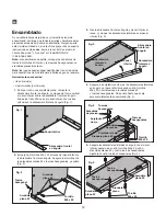
Page 12: ... del panel inferior y la abrazadera frontal en ángulo Asegure los tornillos con las arandelas planas 2 y tuercas hexagonales y apriete Fig 2 3 Gire la abrazadera frontal en ángulo y panel inferior al revés y coloque las abrazaderas laterales en el panel inferior Fig 3 4 Asegure los sujetadores de eje a las abrazaderas laterales en ángulo y al panel inferior usando cuatro tornillos M6 x 30 contratu...

Page 13: ... lateral en ángulo posándolo verticalmente sobre el panel frontal Fig 8 9 Asegure una brida de sujeción entre la abrazadera lateral en ángulo y la abrazadera frontal en ángulo mediante dos tornillos M6 x 25 cuatro arandelas planas 2 y dos tuercas hexagonales Fig 9 Tornillo M6 x 25 Fig 9 Brida de sujeción Arandela plana 2 Tuerca hexagonal Panel lateral Panel frontal Abrazadera frontal en ángulo Abr...

Page 14: ...gúrelo con arandelas planas y tuercas de mariposa Fig 13 15 Coloque el tubo de agarradera por sobre los paneles laterales y alinee los cuatro orificios Instálelo usando cuatro tornillos M6 x 50 y arandelas planas 2 a través de los paneles laterales y tubo de agarradera Asegúrelo con arandelas planas 2 y tuercas de mariposa Fig 14 Fig 10 Panel lateral Abrazadera lateral en ángulo Tornillo M6 x 25 T...

Page 15: ...flada y otra arandela plana 1 sobre del eje Fig 17 19 Asegure la rueda con otro pasador en el orificio exterior en el extremo del eje Fig 18 20 Repita los pasos 17 18 y 19 para ensamblar la otra rueda 21 Apriete las dos tuercas en cada sujetador de eje Fig 18 Fig 14 Tubo de agarradera Tuerca de mariposa Arandela plana 2 Arandela plana 2 Tornillo M6 x 50 Fig 15 Eje Sujetadores de eje Fig 16 Pasador...

Page 16: ...tilla se dañará 8 Guárdela en interiores durante climas extremos y los meses de invierno Nota si una parte necesita reemplazo use solo partes que cumplan con las especificaciones del fabricante Las partes de repuesto que no cumplan con las especificaciones del fabricante pueden resultar en un peligro para la seguridad o bajo rendimiento Servicio y soporte Si su carretilla para jardín Sun Joe SJGC7...

Page 17: ...ración de garantía no autorizada Esta garantía no cubre ningún costo o gasto incurrido por el comprador al proporcionar equipos sustitutos o servicio durante períodos razonables de avería o no utilización de este producto mientras se espera por una pieza de repuesto o nuevo producto bajo esta garantía Las piezas desgastables como correas brocas y cuchillas no están cubiertas por esta garantía y pu...

Page 18: ...s effets néfastes sur la fonction de reproduction 1 Ne jamais transporter de personnes assises ou debout dans le chariot 2 Ne pas laisser les enfants jouer dans le chariot se mettre debout ou grimper dessus 3 Toujours inspecter le chariot avant de l utiliser pour s assurer qu il est en bon état de fonctionnement 4 Remplacer ou réparer immédiatement les pièces endommagées ou usées 5 Avant toute uti...

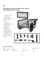
Page 19: ... usage 1 Panneau avant amovible 2 Guidon tubulaire 3 Panneau latéral 2 4 Support de fixation latéral 2 5 Support tubulaire 6 Axe 7 Roue 2 8 Barre de soutien 2 9 Support de fixation avant en U 10 Panneau inférieur 11 Vis M6 x 50 8 12 Vis M6 x 30 4 13 Vis M6 x 25 15 14 Goupille fendue 4 15 Bouton de guidon 8 16 Écrou hexagonal M6 19 17 Rondelle plate n 1 4 18 Rondelle plate n 2 50 19 Rondelle de blo...

Page 20: ...les trois trous dans le panneau inférieur à l aide des trois trous dans le support de fixation avant en U Fig 1 2 Enfoncez trois vis M6 x 25 à travers le panneau inférieur et le support de fixation avant en U Attachez les vis avec les rondelles plates n 2 et les écrous hexagonaux et serrez Fig 2 3 Retournez sur eux mêmes le support de fixation avant en U et le panneau inférieur et posez les suppor...

Page 21: ...ues et des axes 8 Positionnez un panneau latéral contre un support de fixation latéral en le faisant reposer sur la partie supérieure du panneau avant Fig 8 9 Attachez une barre de soutien sur le support de fixation latéral et le support de fixation avant en U à l aide de deux vis M6 x 25 quatre rondelles plates n 2 et deux écrous hexagonaux Fig 9 10 Attachez le panneau latéral au support de fixat...

Page 22: ... Attachez à l aide des rondelles plates n 2 et des boutons de guidon Fig 13 15 Placez le guidon tubulaire sur les panneaux latéraux et alignez les quatre trous Assemblez en faisant passer quatre vis M6 x 50 et rondelles plates n 2 à travers les panneaux latéraux et le guidon tubulaire Attachez à l aide des rondelles plates n 2 et des boutons de guidon Fig 14 Fig 10 Panneau latéral Support de fixat...

Page 23: ... une autre rondelles plates n 1 sur l axe Fig 17 19 Attachez la roue à l aide d une autre goupille fendue sur le trou extérieur à l extrémité de l axe Fig 18 20 Répétez les étapes 17 à 19 pour assembler l autre roue 21 Serrez les deux écrous sur les pattes de fixation d axe des deux côtés Fig 18 Fig 14 Guidon tubulaire Boutons de guidon Rondelle plate n 2 Rondelle plate n 2 Vis M6 x 50 Fig 15 Axe ...

Page 24: ...temps est mauvais ou pendant la saison d hiver remisez l outil à l intérieur Remarque si une pièce doit être remplacée utilisez uniquement les pièces répondant aux spécifications du fabricant Les pièces de rechange qui ne répondent pas aux spécifications peuvent présenter des risques pour la sécurité et être à l origine d un rendement médiocre Entretien réparations et assistance technique Si votre...

Page 25: ...ns non couvertes par la garantie quelles qu elles soient Tous les coûts et dépenses engagés par l acheteur pour obtenir un matériel ou un service de rechange pendant une période raisonnable de mauvais fonctionnement ou de non utilisation de ce produit en attendant une pièce ou un produit de rechange au titre de la présente garantie ne sont pas couverts par la présente garantie Les pièces d usure c...

Page 26: ...NOTES NOTAS 26 ...

Page 27: ...NOTES NOTAS 27 ...

Page 28: ...snowjoe com ...

Reviews: