background image

36 


4.1.6.  Exporting to Excel 


With the 

DataViewer

 software


you have the ability to export the system performance 

information to 

Excel

 for further analysis. 


x

  On the 

Files

 menu in 

DataViewer

, select 

Excel Export

.


DataViewer

 will export the file 

(in .csv format) to a location that you select. 

x

  In 

Excel

, click 

Open

 on the 

File

 menu. (You 

may have to change the “

Files of type

” to 

All 

Files

 to find the exported file.)  

x

  Select Column A in the open file. 

x

  From the 

Data

 menu, click on 

Text to 

Columns


x

  Select 

Delimited

 (then click Next) 

x

  Select 

semicolon

 (click Next) 

x

  In the 

Column/Data format

 you can either leave it as 

General

, or select a different format 

for the entries in each column.  Most commonly, Column A would be changed to 

Date

x

  Click 

Finish


4.1.7.  Send by Outlook Express & Export all Zip 


These two options on the File menu are extremely useful as troubleshooting tools. Those that 
use Outlook Express can use the 

Send by Outlook Express

 feature to transmit the data and 

configuration files to another party for remote assistance and/or diagnosis of a problem.  
Selecting 

Export all Zip

 creates a .zip file of that same information that can be attached to 

any email. 


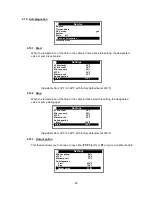
4.1.8.  Settings File: Save

 & 

Settings File: Load 


The 

DataViewer

 software allows the user to design and save more than one system 

configuration on a single SD Card.   
 

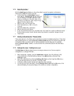
x

  After configuring a system using the 

DataViewer

 software, save the settings to the 

current directory on the SD Card by clicking on the 

Write

 button at the top of the 

Settings

 screen.  

x

  Save the configuration by choosing 

Settings File: Save

 on the drop-down 

File

 menu. 

The file will be saved as an .svg file in the SVG folder.


x

  Configure another system set-up and repeat the above process.


x

  To access any of the saved files, choose 

Settings File: Load

 from the 

File

 menu. This 

action will display the saved settings as the current (or active) configuration.


Summary of Contents for ADVANCED SOLAR CONTROLLER

Page 1: ...ADVANCED SOLAR CONTROLLER...

Page 2: ...performed by qualified personnel in accordance with applicable codes standards and practices SunMaxx Solar is not responsible for any damages or injuries that result from improper installation modific...

Page 3: ...ng 1 7 2 Overheat protection 1 7 3 Freeze Protection 1 8 Sensor Options Page 16 1 8 1 Impulse Flow meter 1 8 2 Grundfos Flow Sensor GDS1 1 8 3 Grundfos Flow Sensor GDS2 Page 17 1 8 4 Flow Monitoring P...

Page 4: ...x 2 17 6 dTMin 3 Operation Menu Page 31 3 1 Automatic and Off operation 3 2 Manual testing operation 4 Operation Hours Menu Page 32 4 1 SD Card option Page 33 4 1 1 Configuring Changing your system se...

Page 5: ...ti stagnation x Permanent memory storage Ambient temperature range for normal operation 32 F 122 F Electrical Protection Installation Category Pollution Degree IP20 II 2 Fuse Power supply Maximum Powe...

Page 6: ...e the or buttons to navigate in the menus The selection cursor will indicate the current submenu Press to enter the selected menu and or to return to the previous menu Not all submenus selections or o...

Page 7: ...ch must be adjusted Note If power supply is lost settings will be retained for 24 hours after that time the clock will have to be reset 1 3 US Version This selection allows you to select the units of...

Page 8: ...ion 1 4 2 System 2 System with 2 tanks 1 pump 1 valve 1 collector array and 3 sensors With this system you can add an extra function with 1 sensor Thermostat Cooling or Anti stagnation function 1 4 3...

Page 9: ...al directions East West and 3 sensors With this system you can add an extra function with 1 sensor Thermostat Cooling or Anti stagnation function 1 4 6 System 6 System with 1 tank 1 pump 1 collector a...

Page 10: ...e as P1 1 4 8 System 8 System with 1 tank 2 pumps 1 external heat exchanger 1 collector array and 3 sensors With this system you can add an extra function with 1 sensor Thermostat Cooling or Anti stag...

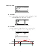
Page 11: ...be used Example This function is available only if selected on the Extra Menu 1 5 2 Cooling Function The cooling function may be used to cool down the primary solar tank during times of high solar ir...

Page 12: ...ttings menu the designated valve or pump is activated x When the collector circuit has cooled down to below the Anti stagnation stop temperature Settings menu the valve or pump will deactivate x See S...

Page 13: ...ee Settings menu Example 1 Additional tank w no auxiliary heat source Example 2 Additional tank w auxiliary heat source This function is available only if selected on the Extra Menu P3 P1 T2 Diffcontr...

Page 14: ...f the protection functions are activated the system will automatically activate when the collector temperature reaches the Maxtemp threshold regardless of the tank temperature settings Maxtemp is adju...

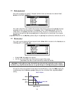
Page 15: ...han 4 F 1 7 2 Overheat protection should only be used in conjunction with Cooling function When set to YES this function will stop all collector circulation P1 and P2 when the collector temperature re...

Page 16: ...ump flow in gallons minute using the or buttons The manufacturer s specification is generally found in the pump literature or on the manufacturer s website 1 8 2 Grundfos Flow Sensor GDS1 The controll...

Page 17: ...the submenu 3 2 Manual testing 1 8 3 Grundfos Flow Sensor GDS2 This input is reserved for connection of a Pressure sensor to monitor the primary circuit Three GF Pressure sensors are supported on the...

Page 18: ...dvanced Solar Control has multiple options for measuring energy Both instantaneous energy kBTU h and accumulated energy kBTU are displayed on the Main Display screen QHUJ LV FDOFXODWHG XVLQJ 7 IORZ DQ...

Page 19: ...2 Cold Sensor Options for which sensor should be used to measure the colder temperature include the following Auto the control will use the default sensors according to the system chosen T2 or T2 and...

Page 20: ...ump with speed control The speed regulation is done by PWM control x Available with GRUNDFOS SOLAR PM type Note If you have selected PWM SC on the Pump P1 or Pump P2 the pump speed will begin to decre...

Page 21: ...use a propylene glycol solution in your system you must specify the concentration on this submenu x To set the concentration press then select a percentage between 0 and 50 in 10 increments with the o...

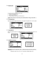
Page 22: ...o zero x Press to highlight the line x Select yes with key x Press repeatedly to return to the main menu Caution This will erase all previously recorded data Power Energy temperature 1 16 Time graph t...

Page 23: ...l always be activated first unless one of the following situations occur NOTE Default setting is No Prio The second tank will become operational when x The priority tank reaches the Maxtemp value ente...

Page 24: ...discussed in sections 1 4 2 System 2 and 1 4 3 System 3 Sets the maximum value of desired water temperature on the tank2 Adjustable from 59 F to 203 F with factory default set at 149 F 2 5 dTMax tank2...

Page 25: ...on the Service menu 1 10 Pump P1 or 1 11 Pump P2 x Highlight Min rev pump and press x Use the or buttons to set the minimum speed of the pumps Adjustable from 30 to 100 with factory default set at 50...

Page 26: ...ector temperature required for solar loading Adjustable from 32 F to 210 F with factory default set at 32 F 2 13 Delay P2 Available for System 7 only User defined setting that dictates the length of t...

Page 27: ...t 104 F 2 14 2 Hysteresis When the water temperature at the top of the system tank T3 exceeds the Start temperature see 2 14 1 above plus the Hysteresis setting P3 will disengage Adjustable from 3 F t...

Page 28: ...em tank T3 falls under the Start temperature see 2 15 1 above minus the Hysteresis setting P3 will disengage Adjustable from 3 F to 54 F with factory default set at 18 F Service English Time and date...

Page 29: ...in the collector falls below this setting the designated valve or pump disengages Adjustable from 32 F to 302 F with factory default set at 200 F 2 16 3 Output option This feature allows you to choos...

Page 30: ...ers above this setting P3 will shutoff and the exchange of heat will stop T3 TC Adjustable from 59 F to 203 F with factory default set at 149 F 2 17 4 Min warm tank The temperature at the top of the e...

Page 31: ...n the Setting menu Section 2 under 2 8 Min rev pump They can be increased from that level to 100 in 5 increments by using the key Note When you exit this menu all values on this menu return to zero Op...

Page 32: ...ttons Adjustable from 1 to 48 hours with factory default set at1 hour Press repeatedly to return to the main menu Operation h Operation _ _ h dT _ _ F Power _ _kBTU h Energy _ _kBTU Volume _ _Gallons...

Page 33: ...check to make sure that the SD Card is solidly installed the SD Card will fit into the Reader if it is turned backwards but the contacts are on the wrong side and the program will not function x Inse...

Page 34: ...set up on your PC x You can now either leave the SD Card turned on in the control to gather system performance data or x remove the SD Card according to the following procedure click on to select the...

Page 35: ...d in the control and switched ON For example x A Solar Control is connected to a system and placed into service at 6 00 A M x An SD Card is inserted into the Solar Control at 9 00 A M and removed at 1...

Page 36: ...seful as troubleshooting tools Those that use Outlook Express can use the Send by Outlook Express feature to transmit the data and configuration files to another party for remote assistance and or dia...

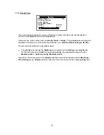
Page 37: ...temp Using the or buttons select Time graph temp and press to highlight the line x Now you can change the scale with the or buttons Adjustable from 1 to 60 minutes with factory default of 5 minutes P...

Page 38: ...id unintentional unauthorized changes System type and Extra Function selection No Thermostat Cooling Anti stagnation or Diffcontrol are inaccessible after the control has been connected to an electric...

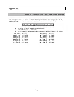
Page 39: ...an Ohmmeter x Use the following chart to determine the approximate temperature at the sensor bulb 14 F 10 C 960 ohms 140 F 60 C 1232 ohms 32 F 0 C 1000 ohms 158 F 70 C 1271 ohms 50 F 10 C 1039 ohms 1...

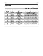
Page 40: ...Pump Thermostat Cooling Ant stagnation 4 Primary 3 way Valve Thermostat Cooling Anti stagnation 5 Primary Variable speed Pump Thermostat Cooling Anti stagnation 6 Primary 3 way Valve Thermostat Coolin...

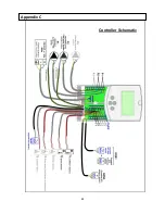
Page 41: ...41 Controller Schematic Appendix C...

Page 42: ...42 Appendix D...

Page 43: ...product subjected to misuse or accidental damage This warranty does not cover the cost of installation diagnosis removal or reinstallation any labor or other material costs loss of use or damage to ot...

Reviews: