6
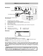
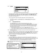
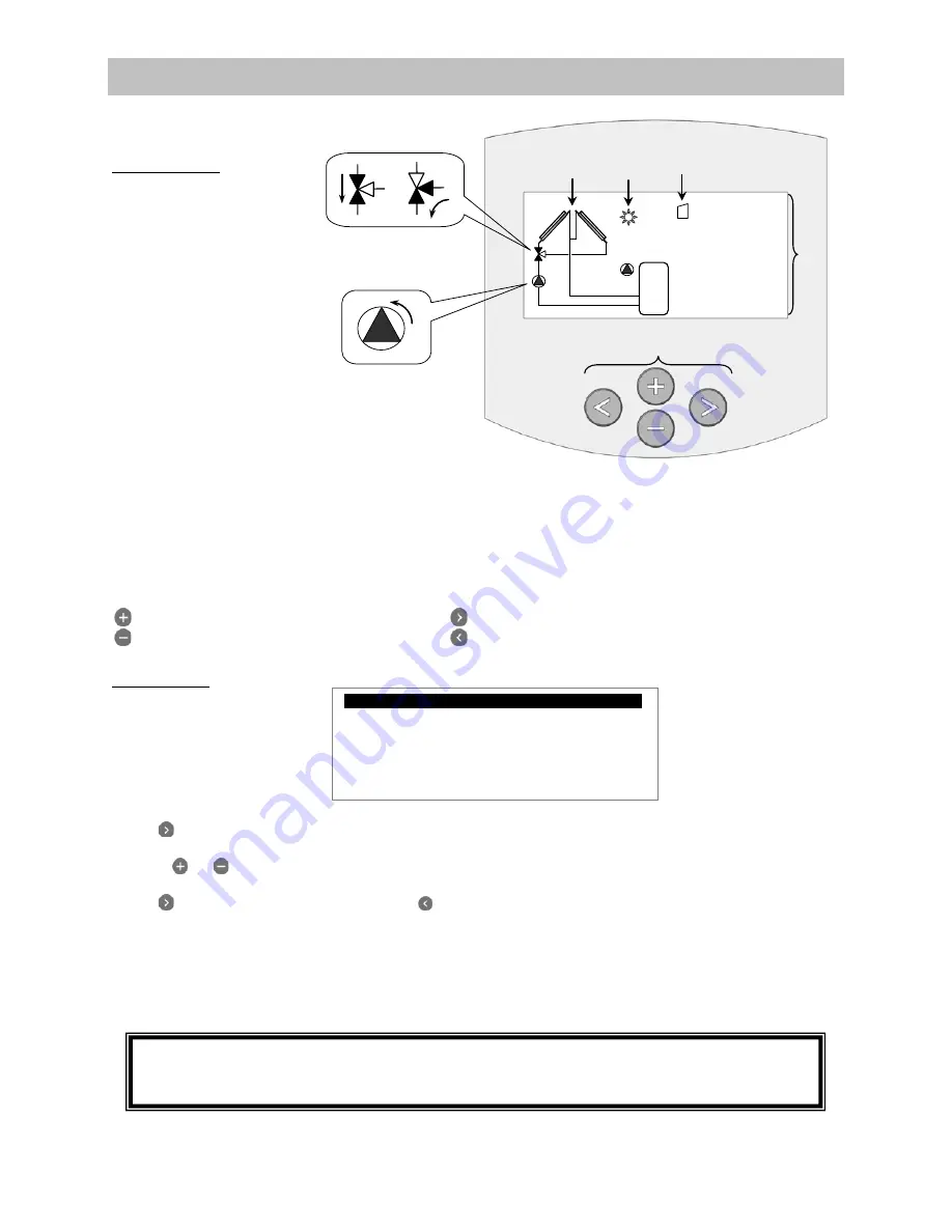
Main Display
Circulation direction
Pump Activation indicator
NOTE: System 4 shown in example; features
typical of all systems.
1:
Simplified drawing of the installation.
-
The pump symbols turn when pumps are activated.
-
The filled triangles on the valve symbol indicate the circulation direction
2:
Solar storage is working.
3:
SD card storage is active.
4:
Sensor temperature readings, pump speed indicators, power and stored energy levels.
A:
Keypad description
Navigation key up or plus key
Navigation key right
Navigation key down or minus key
Navigation key left
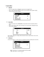
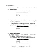
Main menu:
Press
to enter the Navigation Menu.
(The active menu is highlighted in black at the top of the display)
Use the
or
buttons to navigate in the menus. The selection cursor (
¤
)
will indicate the current
submenu
.
Press
to enter the selected menu and/or to return to the previous menu.
Not all submenus, selections, or options discussed in this manual are available on all
systems. Depictions of menus and submenus shown here are representative of their
actual appearance on the control when the same series of settings as is described is
followed.
DISPLAY
(Screen, Keys, Menus)
4
1 2 3
T1_ _ _°F
T2_ _ _°F
T3_ _ _°F
T4_ _ _°F
P1_ _ _ %
_ _ _ BTU/h
_ _ _ BTU
T1
T4
T2
T3
A
SD
¤¤
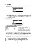
Information n
¤
Service
Settings
Operation
Operation h
Temperatures
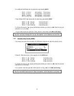
IMPORTANT NOTE:
The factory default setting on the
Operation Menu
is
OFF.
This prevents
system components (
P1
,
P2
,
P3
) from operating until system is set up. To turn on the system,
change the setting to
AUTOMATIC (Active)
. See
Operation
menu /
3.1
for further info.
Summary of Contents for ADVANCED SOLAR CONTROLLER
Page 1: ...ADVANCED SOLAR CONTROLLER...
Page 41: ...41 Controller Schematic Appendix C...
Page 42: ...42 Appendix D...

