background image

SunMaxx Solar  | 5098 NY 206 Bainbridge NY 13733  |  1.877.786.6299  1.877.270.7875  fax  |  www.sunmaxxsolar.com

5. Protections

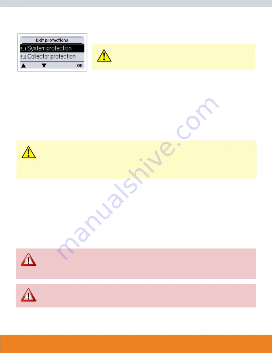
Menu “5. - Protections / Protective functions” can be used to activate and set various protective 
functions.

The menu is closed by pressing “esc” or selecting “Exit”.

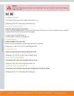
CAUTION

This does not under any circumstances replace the safety facilities to be provided
by the customer!

5.1 SYSTEM PROTECTION


Highest Priority Protection
System protection prevents overheating of system components by automatic shutdown of the solar pump. If “SProt Ton” is exceeded at the collec-
tor, the pump is switched off and stays off. The pump is activated again when the temperature drops below “SProt TOff”.

System protection - Settings range: ON / OFF / Default setting: On
SP T on - Settings range: 60 °C to 150 °C (140 °F to 302 °F) / Default setting: 120 °C (248 °F)
SP T off - Settings range: 50 °C (122 °F) to T on minus 5 °C (23 °C) / Default setting: 115 °C (239 °F)

CAUTION

When system protection is on, the temperature in the idle collector will be very high, thus the pressure in the system will rise and 
can damage your system.

Pay close attention to the instructions of the system manufacturer.

5.2 COLLECTOR PROTECTION


Collector protection prevents overheating of the collector. The pump is switched on to transfer heat from the collector to the storage tank.

If “CP Ton” is exceeded at the collector sensor, the pump is switched on until the temperature reaches “CP Toff” or the temperature “CP Tmax stor-
age” is exceeded in the storage.

Collectorprotection - Settings range: On / Off / Default setting: Off
CP T on - Settings range: 60°C to 150°C (140°F to 302°F) / Default setting: 110°C (230°F)
CP T off - Settings range: 50°C (122°F) to T on minus 5°C (23°F) / Default setting: 100°C (212°F)
CP Storage S(x) Max - Settings range: 30°C to 140°C (86°F to 284°F) / Default setting: 90°C (194°F)

DANGER

When collector protection is active, and both storage and pool are present, the storage is heated up to “CP Storage S(x) Max” be-
yond Tmax S2 (see “4.2. - Tmax S (X)” on page 25) which can result in scalding and system damage. When only a pool is used, the 
pool is not used for collector protection.

DANGER

System protection has a higher priority than collector protection. Even when the switch on conditions for collector protection are 
present, the solar pump will be switched off when SP T on is reached.

Summary of Contents for SmartMaxx-Pro-L4

Page 1: ...INSTALLATION GUIDE SMARTMAXX SOLAR CONTROLLERS WWW SUNMAXXSOLAR COM MODEL NUMBER SmartMaxx Pro L4 SmartMaxx Pro XL6D X...

Page 2: ...ting Modes 18 3 Settings 18 4 Protections 21 5 Special Functions 23 6 Menu Lock 40 7 Service Values 40 8 Languages 41 9 Malfunctions 41 Z This Manual Applies To The Following Hardware Versions Version...

Page 3: ...WARE VERSIONS Version 2 2 mechanical relays 1 on off 1 change over contact 1 electronic relay for speed control of standard pumps 1 PWM 0 10V for high efficency pumps 5 PT1000 temperature sensor input...

Page 4: ...nce of the unit may only be carried out by specialists who possess the appropriate training For the user Make sure that the specialist gives you detailed information on the function and operation of t...

Page 5: ...wever any injury to persons or material damage that is attributable to one or more of the following causes Failure to observe these installation and operating instructions Improper installation commis...

Page 6: ...320F to 1400F Air Humidity For Controller Operation Max 85 rel humidity 770F For Transport Storage no moisture condensation Other Specifications Dimensions Housing Design 3 Part ABS Plastic Installati...

Page 7: ...lues Analysis and monitoring of the system by means of statistical graphics etc Individual configuration of special functions Extensive setting menus with explanations Menu block can be activated to p...

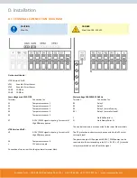
Page 8: ...unit must not be stripped by more than 55mm and the cable jacket must each into the housing just to the other side of the strain relief CAUTION Controller and VFS sensor have to have the same ground...

Page 9: ...hat the wall surface is as even as possible so that the housing does not become distorted when it is screwed on 5 Using a drill and size 6 bit drill 3 holes at the points marked on the wall and push i...

Page 10: ...es with Pt1000 temperature sensors which are accurate to the degree thus ensuring optimal control of system functions CAUTION The temperature sensor cables must be routed separately from mains voltage...

Page 11: ...e g for control of High Efficiency pumps LTDC Version V3 V4 V2 0 10V PWM signal output e g for control of High Efficiency pumps S6 Temperature sensor 6 12V power supply Connection of sensor earth to t...

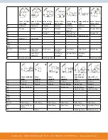
Page 12: ...V1 Solar Pump Solar Pump Charge Pump Pump Pump 1 R2 R3 Switching Valve Thermostat Stop Valve Solar W Pool WT Sensor Solar Thermostat Solar 2 Zone Storage Valve Solar Return Flow Increase Solar Bypass...

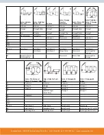
Page 13: ...Pump Collector 1 Solar Pump Solar Pump Storage 1 Solar Pump Solar Pump Solar Pump R2 Solar Pump Collector 2 Solar Pump Storage 2 Transfer Pump Secondary Pump R3 Switching Valve Switching Valve Switchi...

Page 14: ...or 2 S6 VFS1 VFS2 R1 V1 Solar Pump Solar Pump Solar Pump 1 Solar Pump Solar Pump Solar Pump R2 Solar Pump Solar Pump 2 Charge Pump Thermostat Switching Valve Collector R3 Secondary Pump Switching Valv...

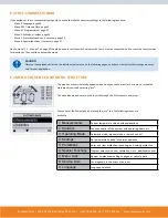
Page 15: ...tion of fl ow in black Collector Storage Pool Temperature sensor Heat exchanger Load pause see Load time Warning error message New information available Logging is active More symbols can be found in...

Page 16: ...2 minutes or when the main menu is exited by pressing esc The up and down buttons are used to scroll through the list of sensors and relays You can enter the Main menu by pressing the esc key The fol...

Page 17: ...monitoring of the system The menu is closed by pressing esc or selecting Exit statistics CAUTION For analysis of the system data it is essential for the time to be set accurately on the controller Pl...

Page 18: ...en set The measured temperatures are also shown to provide an overview and function control DANGER When operating mode Manual is activated the current temperatures and the selected parameters are no l...

Page 19: ...g or damage to the system Scalding protection must be provided by the customer 4 3 TMAX SB Switch off temperature at pool sensor If this value is exceeded at the applicable sensor the controller switc...

Page 20: ...minutes CAUTION If the set temperature difference is too small this may result in ineffective operation depending on the system and sensor posi tions Special switching conditions apply for speed contr...

Page 21: ...and can damage your system Pay close attention to the instructions of the system manufacturer 5 2 COLLECTOR PROTECTION Collector protection prevents overheating of the collector The pump is switched o...

Page 22: ...on continuously If the collector temperature then exceeds the value Frost stage 2 by 2 C then the pump switches off again Frost protection setting range on off default setting off Frost stage 1 setti...

Page 23: ...once during initial commissioning by the specialist Incorrect program selection can lead to unpredictable errors 6 2 PUMP MENU This menu contains the settings for 0 10V or PWM pump 6 2 1 Type Of Pump...

Page 24: ...nk is greater than the set value then the speed is increased by one stage after the control time elapses If the temperature difference T between the reference sensors is below the set value then the s...

Page 25: ...greater or lesser extent depending on the system pump and pump stage 100 is the maximum possible voltage frequency of the controller 6 3 6 Setpoint This value is the control setpoint for Mode 3 see 6...

Page 26: ...selected in this menu Do not install in the return flow Settings range S1 S8 VFS1 VFS2 Default setting none 6 4 2 Thermostat Thermostat is used for time and temperature controlled additional heating...

Page 27: ...ermostat sensor 1 the relay is switched on and heats up to T eco hysteresis Settings range 0 C 100 C 32 F to 212 F Default setting 40 C 104 F 6 4 2 6 Storage For Energy saving mode Loading this storag...

Page 28: ...tivity times Set the desired periods of time when the cooling should be active 3 periods can be set per day settings can also be copied to other days Outside the set times the cooling function is swit...

Page 29: ...reference sensor the relay is switched on Settings range 100 C to 180 C 212 F to 356 F Default 120 C 248 F 6 4 6 2 Hys Min When the temperature falls below Tmax field Hys min the relay is switched of...

Page 30: ...sor 2 When a second sensor is connected both sensors must reach and hold the setpoint temperature for the residence time for a successful heat up Settings range S1 S8 VFS1 2 Active storage Default set...

Page 31: ...Transfer Off the relay is switched off again On Settings range 5 20 K Default setting 8 K Off Settings range 2 K to T Ein Default setting 4 K 6 4 8 2 Setpoint Setpoint temperature of the target stora...

Page 32: ...Heat source sensor for Difference function This determines the sensor for the heat source Settings range S1 S8 VFS1 2 Active storage Default setting none 6 4 9 3 Diff Tmin Minimum temperature at sourc...

Page 33: ...the storage If this is exceeded the relay is switched off Settings range Off to 100 C 212 F Default setting 70 C 168 F This determines the sensor that is used as boiler sensor Settings range S1 S8 VF...

Page 34: ...1 6 bar 0 2 5 bar 0 4 bar 0 6 bar 0 10 bar Default setting Off 6 4 12 2 RPS1 RPS2 Minimum pressure If this value is undershot an error message is displayed and the relay is switched on Settings range...

Page 35: ...llowup Time Relay is always switched on 6 4 15 Always On Heat circuit pump is controlled with a fixed hysteresis of 1 for setpoint temperature 30 seconds Switch on and Switch off delay is fixed set ti...

Page 36: ...storage temperature are used a dif ference to the flow respectively return flow temperature can be compensated by changing Offset T accordingly Example Displayed collector temp 40 C 104 F measured fl...

Page 37: ...30 C 86 F measured return temperature 31 C 87 F results in a correction value of 20 displayed T 10K real T 8K 20 correction Settings range 50 to 50 Default setting 0 6 5 1 6 Offset T 6 5 2 VFS X The...

Page 38: ...PS2 Minimum pressure If this value is undershot an error message is displayed and the relay is switched on Settings range Off 0 0 to 1 6 bar Default setting 0 0 6 6 1 2 Pmin Maximum pressure If this v...

Page 39: ...m tube collectors it may occur that the measurement value acquisition at the collector sensor oc curs too slowly or too inaccurately because the sensor is often not at the hottest location When the st...

Page 40: ...is displayed Settings range F or C Default C 7 Menu Lock Menu 7 Menu lock can be used to secure the controller against unintentional changing of the set values The menu is closed by pressing esc or se...

Page 41: ...alist in the event of an error Possible Error Messages Notes For The Specialist Sensor X Defective Means that either the sensor the sensor input at the controller or the connecting cable is was defect...

Page 42: ...hange the defective fuse for a new one locate the external source of the error e g pump and exchange it Then first recommission the controller and check the function of the switch outputs in manual mo...

Page 43: ...ofile has been selected J 2 OUTPUT SIGNAL This menu determines the type of pump used Solar pumps perform at their highest power when the signal is also maxed heating pump on the other hand are set to...

Page 44: ...Solar 5 0 to 10 0 V Default setting 10 0 V Heating 0 0 to 5 0 V Default setting 0 0 V J 9 SPEED WHEN ON This menu determines the calculated and displayed speed of the pump If e g 30 is set here and th...

Page 45: ...service values at least once after commissioning has been successfully completed In the event of uncertainty as to the control response or malfunctions the service values are a proven and successful m...

Page 46: ...5098 NY 206 Bainbridge NY 13733 1 877 786 6299 1 888 270 7875 fax WWW SUNMAXXSOLAR COM Hydraulic Variant Set Commissioned On Commissioned By Notes V 2016 2 29...

Reviews: