background image

5


ASSEMBLY INSTRUCTIONS 

We value your experience using Sunny Health and Fitness products. For assistance with parts  
or troubleshooting, please contact us at support@sunnyhealthfitness.com or 1-877-90SUNNY  
(877-907-8669). 


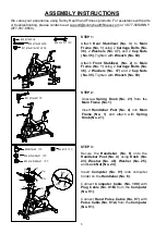
STEP 1: 

Attach 

Rear  Stabilizer  (No.  3)

  to 

Main 

Frame (No. 1)

 using 2 

Carriage Bolts (No. 

36)

,  2 

Washers  (No.  37)

,  and 2 

Cap  Nuts 

(No. 35)

. Tighten with 

Wrench (No. 89)

 
Attach 

Front  Stabilizer  (No.  2)

  to 

Main 

Frame (No. 1)

 using 2 

Carriage Bolts (No. 

36)

,  2 

Washers  (No.  37)

  and  2 

Cap  Nuts 

(No. 35)

. Tighten with 

Wrench (No. 89)


#35 M10 4PCS


#36 M10x55 4PCS


#37 d10xФ19x1.5T 4PCS 

#23 M10x28   1PC 

#46 d10xФ29x2T   1PC 

#25 d19.5xФ38x2T   1PC 


STEP 2: 

Unscrew 

Spring  Knob  (No.  21)

  from  the 

Main Frame (No. 1)

 
Insert 

Handlebar  Post  (No.  4) 

into 

Main 

Frame  (No.  1) 

and  attach  with 

Spring 

Knob (No. 21)


STEP 3: 

Secure  the 

Handlebar  (No.  6)

  onto  the 

Handlebar  Post  (No.  4)

  using 

Knob  (No. 

23)

Washer  (No.  46)

Washer  (No.  25)

and 

Lock Nut (No. 24)

 
Insert 

Computer  (No.  91) 

onto  computer 

holder on the 

Handlebar (No. 6)

.


Connect 

Computer  Cable  (No.  100)

  with 

Plug  Cable  (No.  91B) 

from  the 

Computer 

(No. 91)

;


Connect 

Hand  Pulse  Cable  (No.  97) 

with


Pulse Cable (No. 91A) 

from the 

Computer 

(No. 91)


#21 M16x26 1PC 

#35 M10 4PCS


#36 M10x55 4PCS


#37 d10xФ19x1.5T 4PCS 


#23 M10x28   1PC 


#46 d10xФ29x2T   1PC 


#25 d19.5xФ38x2T   1PC 


#24 M10   1PC


#89 S14 S17 1PC


Summary of Contents for EVOLUTION PRO II

Page 1: ...E SF B1986 USER MANUAL IMPORTANT Please retain owner s manual for maintenance and adjustment instructions Your satisfaction is very important to us PLEASE DO NOT RETURN UNTIL YOU HAVE CONTACTED US support sunnyhealthfitness com or 1 877 90SUNNY 877 907 8669 ...

Page 2: ...he equipment The equipment is designed for adult use only 4 Use the equipment on a solid flat level surface with a protective cover for your floor or carpet To ensure safety the equipment should have at least 2 feet 60 CM of free space all around it 5 Ensure that all nuts and bolts are securely tightened before using the equipment The safety of the equipment can only be maintained if it is regular...

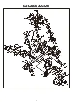
Page 3: ...2 EXPLODED DIAGRAM ...

Page 4: ...ion Control Knob M10 1 24 Lock Nut M10 1 78 Screw M5x15 4 25 Washer d19 5xФ38x2T 1 79 Bolt M5x10 2 26R Right Plastic Cover For Magnet 1 80 Self tapping Screw M4 5x25 5 26L Left Plastic Cover For Magnet 1 81 Plastic Cap 1 27 Support Bar 20x20x1 4T 1 82 Washer 12x24x1 5T 2 28 Magnet Bracket 1 83 Washer Φ5 2 29 Brake Rod 1 84 Plastic Cover 1 30 Fixed Cover 1 85 Washer 10x20x2T 1 31 Groove Fastener 2 ...

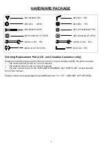
Page 5: ...f manual The product name found on cover of manual The part number found on the EXPLODED DIAGRAM and PARTS LIST found near the front of the manual Please contact us at support sunnyhealthfitness com or 1 877 90SUNNY 877 907 8669 23 M10X28 1PC 22 M10 1PC 35 M10 4PCS 24 M10 1PC 36 M10x55 4PCS 25 d19 5xФ38x2T 1PC 37 d10xФ19x1 5T 4PCS 46 d10xФ29x2T 2PCS 89 S14 S17 1PC 90 S13 S15 1PC 93 S14 S17 S19 1PC...

Page 6: ...S 36 M10x55 4PCS 37 d10xФ19x1 5T 4PCS 23 M10x28 1PC 46 d10xФ29x2T 1PC 25 d19 5xФ38x2T 1PC STEP 2 Unscrew Spring Knob No 21 from the Main Frame No 1 Insert Handlebar Post No 4 into Main Frame No 1 and attach with Spring Knob No 21 STEP 3 Secure the Handlebar No 6 onto the Handlebar Post No 4 using Knob No 23 Washer No 46 Washer No 25 and Lock Nut No 24 Insert Computer No 91 onto computer holder on ...

Page 7: ...R with Spanner No 93 Remove the Left Lock Nut No 92L located on the Left Pedal No 94L Screw the Left Pedal No 94L counter clockwise into Left Crank No 18L Once the pedal is in place use Wrench No 90 to hold the bolt of the pedal Securely screw the Left Lock Nut No 92L clockwise into the thread end of the Left Pedal No 94L with Spanner No 93 STEP 6 Adjust the bolt on the Bottle Holder No 48 with pr...

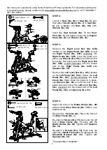
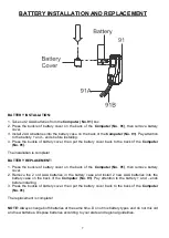
Page 8: ... The installation is complete BATTERY REPLACEMENT 1 Press the buckle of battery cover on the back of the Computer No 91 then remove battery cover 2 Remove the 2 old AAA batteries in the battery case and install 2 new AAA batteries into the battery case on the back of the Computer No 91 Pay attention to the battery and ends before installing 3 Press the buckle of battery cover then put the battery ...

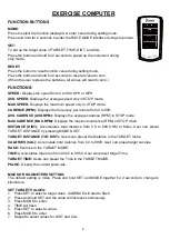
Page 9: ...e average cadence RPM in STOP mode MAX CADENCE MAX RPM Displays the maximum cadence RPM in STOP mode DISTANCE DIST Accumulates total distance from 0 0 to 999 9 KM or Miles User can preset TARGET DISTANCE by pressing MODE SET TARGET DISTANCE TGT DIST Users can preset the Distance in the TARGET mode CALORIES CAL Accumulate total Calories from 0 0 to 9999 User can preset target calories RACE Exercise...

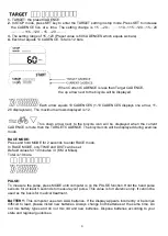
Page 10: ...mode RACE MODE Press and hold MODE for 2 seconds to enter RACE mode In RACE MODE only TIME and DIST can be set Default values for 10 minutes 4 KM or Miles Total is 10 bars PULSE To measure the pulse press MODE until computer is on the PULSE function Hold the hand pulse sensors for at least 5 seconds to measure your pulse This value is for reference only It cannot be used as the basis for medical t...

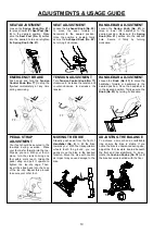
Page 11: ... as impact may cause damage to the bike SEAT ADJUSTMENT Loosen the Spring Knob No 21 to raise or lower the Seat Post No 5 to the desired position Make sure the Seat Post No 5 settles into the desired hole and retighten the Spring Knob No 21 SEAT ADJUSTMENT Loosen the L shaped Knob No 22 to move the seat forward or backward to the desired position Once the position is located firmly secure the L sh...

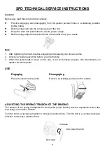
Page 12: ...g one shoe at a time 2 Check your pedals each time before you ride the bike 3 When the pedal starts to wear on the axle it will not function properly We recommend you replace the entire pedal USE Engaging Disengaging Press the cleat into the pedal Remove by twisting your heel to the outside ADJUSTING THE SPRING TENSION OF THE BINDING The tension of the spring is adjusted for each pedal top bottom ...

Page 13: ...ive damage 3 Clean and lubricate pop pin assemblies Pull on the pin and spray a small amount of lubricant onto the shaft 4 Tighten the seat hardware to make sure the seat is level and centered 5 Brush and treat the resistance pads Remove any foreign material that may have collected on the pads Spray the pads with silicone lubricant This helps to reduce noise from friction between the pads and the ...

Page 14: ......

Reviews: