5
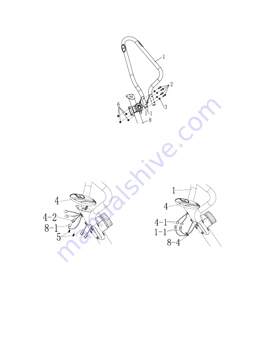
STEP: 2
Attach the
Handlebar (No. 1)
to the
Main Frame (No. 8)
using 4
Screws (No. 2)
, 4
Washers (No. 3)
and 4
Nuts (No. 6)
, tighten using
Allen Wrench (A)
and
Spanner (B)
.
STEP: 3
Insert the Meter Wires (4-1 and 4-2) through the hole of the meter bracket located along
the top end of the
Main Frame (No. 8)
.
Connect the Meter Wire (4-2) to the connecting wire (8-1). Then using 2
Screws (No. 5)
and
Allen Wrench (A)
attach and secure the
Meter (No. 4)
to the meter bracket located
on the
Main Frame (No. 8).
Connect the pulse sensor wires (1-1) from the handlebar to the Meter Wires (4-1).
Then put on the
Clamp
(
No.8-4
).
Summary of Contents for SF-B0419
Page 3: ...2 EXPLODED DRAWING ...


