ASSEMBLY INSTRUCTIONS
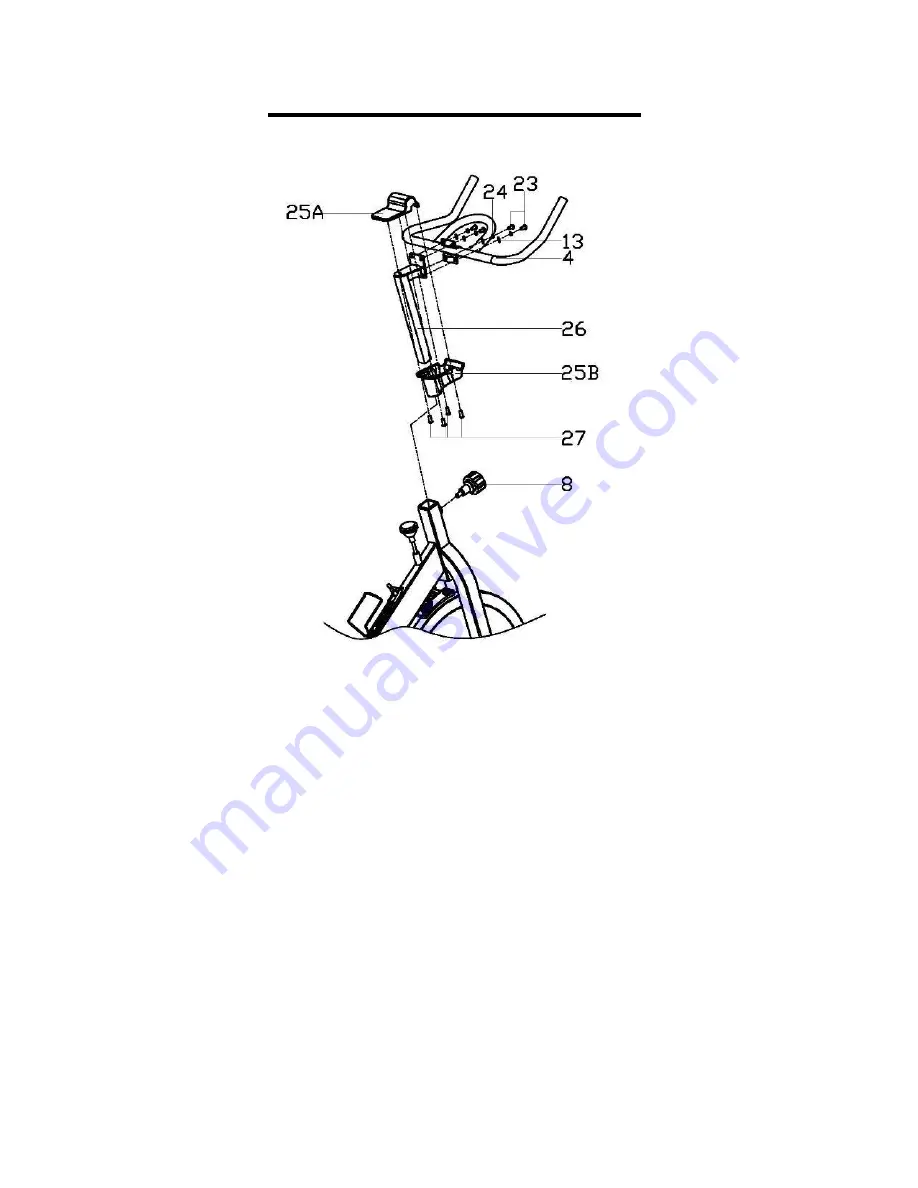
STEP 2:
Attach the
Handlebar (No. 4)
to the
Handlebar Post (No. 26)
and secure with
Allen Bolts
(No. 23)
,
Flat Washers (No. 13)
and
Spring Washers (No. 24)
.
Set the
Lower Handlebar Cover (No. 25B)
on the square tube of the
Handlebar Post (No.
26)
in alignment with the four grooves on the mouth of the
Lower Handlebar Cover (No.
25B)
. Slide the
Lower Handlebar Cover (No. 25B)
onto the top of the square tube of the
Handlebar Post (No. 26)
and rotate the cover 45 degrees to align it with the
Handlebar (No.
4)
.
Use
Phillips Screws (No. 27)
to fix the
Top Cover (No. 25A)
to the
Lower Handlebar
Cover (No. 25B)
so that the
Handlebar (No. 4)
and
Handlebar Post (No. 26)
are in
between the
Handlebar Covers (No. 25A/B)
. Turn and loosen the
Knob (No. 8)
, pull the
pin, and insert the handlebar assembly into the main frame simultaneously. Ensure the pin
settles into the desired hole before securing the
Knob (No. 8)
.
5
Summary of Contents for SF-B1001
Page 3: ...EXPLODED DRAWING 2 ...


