background image


ASSEMBLY INSTRUCTIONS 


We  value  your  experience  using  Sunny  Health  and  Fitness  products.  For  assistance  with  parts  or 
troubleshooting, please contact us at support@sunnyhealthfitness.com or 1-877-90SUNNY (877-907-
8669). 


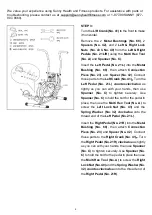
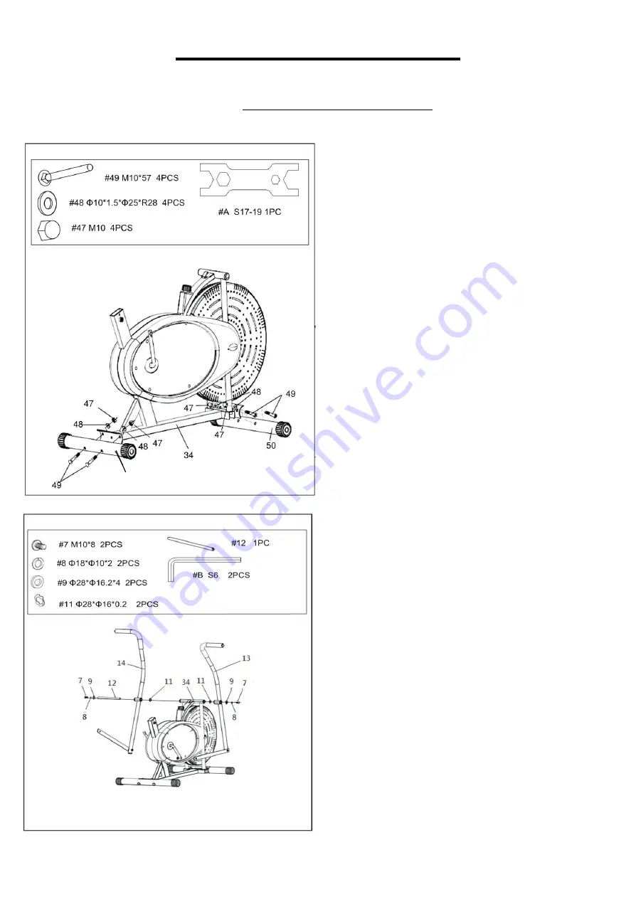
STEP 1: 

Position the 

Front Stabilizer (No. 50) 

in front of 

Main Frame (No. 34)

. Make sure the UP label 

is facing up and the bolt holes align. Attach the 

Front Stabilizer (No. 50) 

onto the 

Main Frame 

(No. 34) 

with 2 

Domed Nuts (No. 47)

, 2 

Curve 

Washers  (No.  48),

  and  2 

Bolts  (No.  49)

Tighten  and  secure  with  the 

Multi  Hex  Tool 

(No. A)


Position the 

Rear Stabilizer (No. 51) 

behind the 

Main Frame (No. 34) 

and align the bolt holes. 

Attach  the 

Rear  Stabilizer  (No.  51) 

onto  the 

Main Frame (No. 34) 

with 2 

Domed Nuts (No. 

47)

,  2 

Curve  Washers  (No.  48)

,  and  2 

Bolts 

(No. 49)

. Secure and tighten with the 

Multi Hex 

Tool (No. A)

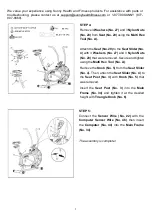
STEP 2: 

Remove  2 

Hinge  Screws  (No.  7)

,  2 

Spring 

Washers (No. 8)

, 2 

D Shape Washers (No. 9)

,


and  2

  Wave  Washers  (No.  11) 

from  the


Rotation Rod (No. 12) 

 with 2 

Allen Wrenches 

(No. B). 


Insert the 

Rotation Rod (No. 12) 

into the torque 

tube of the 

Main Frame (No. 34) 

with 2

 Wave 

Washers  (No.  11)

.  Attach  the 

Right  &  Left 


Handrail  Arms  (No.  13 

&

  No.  14) 

onto  the 

Rotation  Rod  (No.  12)

  with  2 

Hinge  Screws 

(No.  7)

,  2 

Spring  Washers  (No.  8)

,  and  2 

Shape  Washers  (No.  9) 

that  were  removed. 

Secure and tighten with 2 

Allen Wrenches (No. 

B)

.  

51 

Summary of Contents for SF-B2618

Page 1: ...F B2618 IMPORTANT Please retain owner s manual for maintenance and adjustment instructions Your satisfaction is very important to us PLEASE DO NOT RETURN UNTIL YOU HAVE CONTACTED US support sunnyhealthfitness com or 1 877 90SUNNY 877 907 8669 ...

Page 2: ...e equipment The equipment is designed for adult use only 4 Use the equipment on a solid flat level surface with a protective cover for your floor or carpet To ensure safety the equipment should have at least 2 feet 60 CM of free space all around it 5 Ensure that all nuts and bolts are securely tightened before using the equipment The safety of the equipment can only be maintained if it is regularl...

Page 3: ...2 EXPLODED DIAGRAM ...

Page 4: ...Bushing 1 50 Front Stabilizer Φ50 1 5 470 1 16 Fan Wheel 1 51 Rear Stabilizer Φ50 1 5 470 1 17 Fan Wheel Axle 1 52 Washer Φ40 Φ24 3 1 18 Hexagon Nut M10 1 5 53 Notched Bearing Nut 15 16 1 19 Sensor 1 54 Bearing Cup 2 20 Seat 1 55 Bearing 2 21L Left Pedal 1 56 Slotted Bearing Nut 7 8 1 21R Right Pedal 1 57 Washer Φ34 5 Φ23 Φ2 5 1 22 Sensor Wire 1 58 Hexagon Nut 7 8 1 23 Connection Piece 2 59 Right ...

Page 5: ... in order for us to accurately identify the part s needed The model number found on cover of manual The product name found on cover of manual The part number found on the EXPLODED DIAGRAM and PARTS LIST found near the front of the manual Please contact us at support sunnyhealthfitness com or 1 877 90SUNNY 877 907 8669 ...

Page 6: ...on the Rear Stabilizer No 51 behind the Main Frame No 34 and align the bolt holes Attach the Rear Stabilizer No 51 onto the Main Frame No 34 with 2 Domed Nuts No 47 2 Curve Washers No 48 and 2 Bolts No 49 Secure and tighten with the Multi Hex Tool No A STEP 2 Remove 2 Hinge Screws No 7 2 Spring Washers No 8 2 D Shape Washers No 9 and 2 Wave Washers No 11 from the Rotation Rod No 12 with 2 Allen Wr...

Page 7: ...dal No 21L counter clockwise as tightly as you can with your hands then use Spanner No C to tighten securely Use Spanner No C to hold the bolt for the pedal in place then use the Multi Hex Tool No A to screw the Left Lock Nut No 43 and the Spring Washer No 32 clockwise onto the thread end of the Left Pedal No 21L Insert the Right Pedal No 21R into the Metal Bushing No 68 then attach Connection Pie...

Page 8: ...t Slider No 4 with 3 Washers No 27 and 3 Nylon Nuts No 28 that were removed Secure and tighten using the Multi Hex Tool No A Remove the Knob No 5 from the Seat Slider No 4 Then attach the Seat Slider No 4 to the Seat Post No 3 with Knob No 5 that was removed Insert the Seat Post No 3 into the Main Frame No 34 and tighten it at the desired height with Triangle Knob No 6 STEP 5 Connect the Sensor Wi...

Page 9: ...rease the level of resistance Rotate the Tension Control Knob No 45 counter clockwise to decrease the level of resistance MOVING THE BIKE To move the bike hold the Right Left Handrail Arm No 13 No 14 and tilt the bike until the Movable Wheels located on the Front Stabilizer No 50 touch the ground With the wheels on the ground you can transport the bike to the desired location with ease CLEANING Th...

Page 10: ... the pointer on the function you wish to select begins to flash Once locked only the selected function will be displayed Press the MODE button to choose another function FUNCTIONS TIME Counts the total time of an exercise from start to finish SPEED Displays the current speed being obtained DISTANCE Counts the total distance of an exercise from start to finish CALORIES Counts the number of total ca...

Page 11: ...10 ...

Reviews: