9
ALTERNATE INSTALLATION
METHOD:
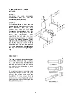
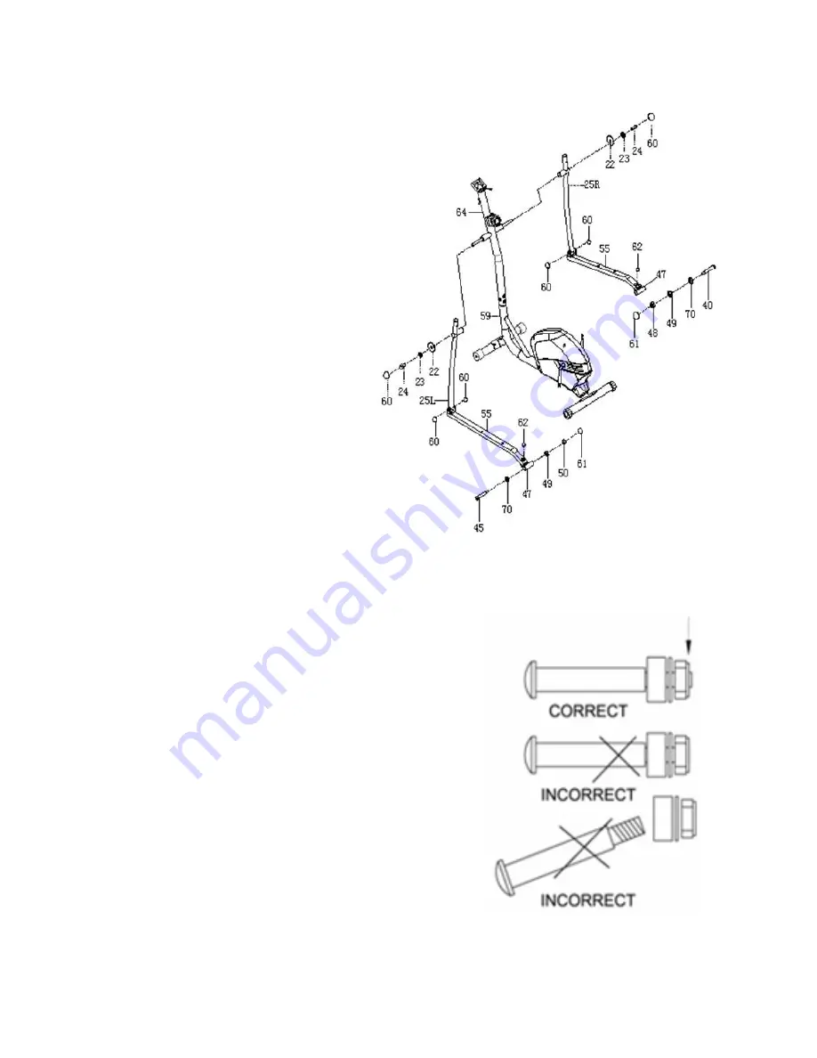
STEP: 1
Disconnect the
Link Connector
Combination (No. 47)
from the
Connecting Rod (No. 55)
.
STEP: 2
Insert
Hinge Bolt L (No. 45)
and
Hinge Bolt R (No. 40)
through the
Wave Washers (No. 70)
, then
through the hole of the
Link
Connector Combination (No. 47)
,
then screw the Hinge Bolt into the
crank
arm.
(Remember
when
assembling the left side, you must
screw counter-clockwise to tighten).
Connect the
Spring Washers (No.
49)
,
Nylon Nut L (No. 50)
and
Nylon
Nut R (No. 48)
and attach the
Ball
Caps (No. 61)
. You can now reattach
the
Link Connector Combination
(No. 47)
to the
Connecting Rod (No.
55)
.
IMPORTANT:
The
Left
and
Right Hinge Bolts (No.
45
and
No. 40)
must fully penetrate
the
Link Connector Combination
(No. 47)
and crank. This will ensure
the stability and durability of your
Elliptical Trainer.
To install the hinge bolt properly, keep
it perfectly straight as the bolt goes
through the pedal arms and the
crankshaft. If the hinge bolt is
connected to the crankshaft at an
angle, damage to both the hinge and
crankshaft may occur.
Summary of Contents for SF-E3416
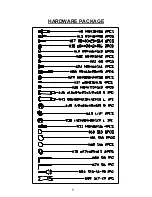
Page 6: ...5 HARDWARE PACKAGE ...


