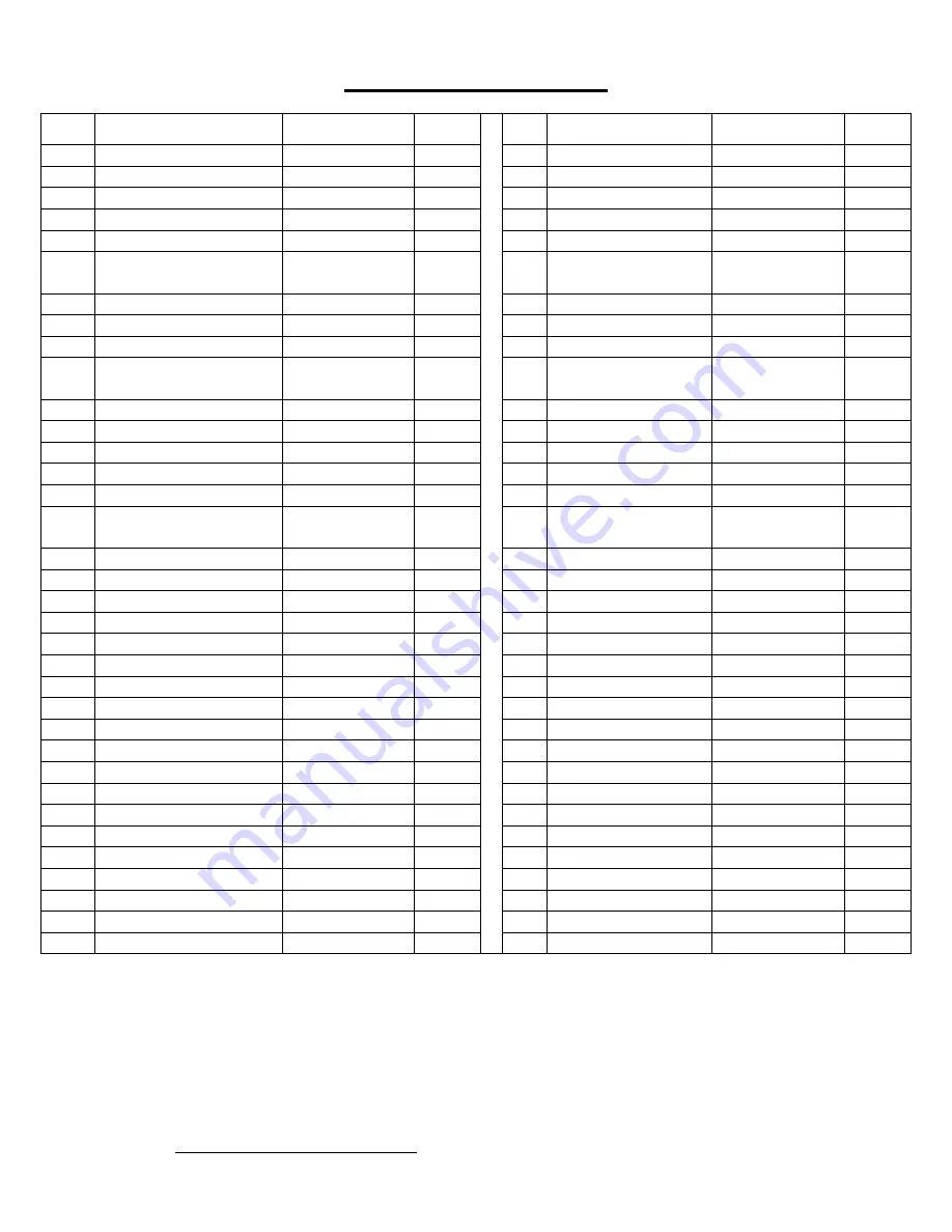
background image


LISTA DE PIEZAS


n.° 

Descripción 

Espec. 

Cant. 


n.° 

Descripción 

Espec. 

Cant. 

Estructura Principal 


35 

Arandela Plana 

Φ8.2*Φ16*1.5


2R 

Estructura del Pedal (R) 


36 

Manguito 


2L 

Estructura del Pedal (L) 


37 

Cojinete 

6000 

Manivela 


38 

Arandela 

Φ10.2*Φ20*1.5


Tablero Magnético 


39 

Tornillo 

M10*20*12 

Eje de Rueda de 
Transmisión 


40 

Tuerca de Nailon 

M10 

Eje para Manivela 


41 

Resorte 


7L/R 

Pedal 


42 

Abrazadera de Cable   

8L/R 

Cubierta de Cinta 


43 

Tornillo 

M6*12 

Perilla de Control de 
Tensión 


44 

Arandela Plana 

Φ6.4*Φ12*1.2


10 

Medidor 


45 

Tuerca 

M5 

11 

Rueda de Inercia 


46 

Manguito 


12 

Arandela Ondulada 

Φ10.2*Φ15*0.2


47 

Imán 


13 

Rueda de Transmisión 


48 

Perno 

M8*35*15 

14 

Rueda Deslizante 


49 

Inductor 


15 

Almohadilla 
Antideslizante EVA 


50 

Asiento del Inductor 


16 

Tapa de Extremo 


51 

Resorte 


17 

Perno 

M8*45*15 

52 

Huso 


18 

Envoltura de Aleación 


53 

Tornillo 

ST3.5*15 

19 

Arandela Plana 

Φ8.2*Φ25*1.5


54 

Tapa de Extremo 


20 

Tornillo 

M8*16 

55 

Rueda de Transporte   

21 

Perno Hexagonal 

M8*45*15 

56 

Perno 

M8*40*15 

22 

Cojinete 


57 

Tapa de Extremo 


23 

Tuerca de Nailon 

M8 

11 

58 

Manubrio 


24 

Tornillo 

ST4.2*15 

14 

59 

Agarre de Espuma 


25 

Tuerca de Brida 

M10 

60 

Tapa de Extremo 


26 

Tapa de Extremo 


61 

Barral Vertical 


27 

Arandela Ondulada 

Φ17*Φ21*0.4


62 

Perilla Triangular 


28 

Perno 

M6*12 

63 

Buje 


29 

Tuerca de Nailon 

M6 

64 

Tornillo 

M8*15 

30 

Rueda de Cinta 


65 

Arandela en Arco 

Φ8.2*Φ16*1.5


31 

Cinta 

J300 

66 

Arandela 

Φ8.1*Φ10.2*2


32 

Clip C 


67 

Arandela 

Φ

16

.2*Φ

28*1.2 

33 

Cojinete 

6003 

68 

Llave Allen 

S5 

34 

Tornillo 

M5*15 


Pedido de piezas de repuesto (solo para clientes de EE. UU. y Canadá) 

Proporcione la siguiente información para que podamos identificar con precisión las piezas necesarias: 

  El número de modelo (se encuentra en la portada del manual).


  El nombre del producto (se encuentra en la portada del manual).


  El número de pieza que se encuentra en el “ESQUEMA DE LAS PIEZAS” y en la “LISTA DE PIEZAS” (se 

encuentra al principio del manual).


Contáctenos en support@sunnyhealthfitness.com o 1-877-90SUNNY (877-907-8669). 

Summary of Contents for SF-E3988

Page 1: ...very important to us PLEASE DO NOT RETURN UNTIL YOU HAVE CONTACTED US support sunnyhealthfitness com or 1 877 90SUNNY 877 907 8669 Español Page 10 14 IMPORTANTE Conserve el manual del propietario para las instrucciones de mantenimiento y ajuste Su satisfacción es muy importante para nosotros NO DEVUELVA HASTA HABERNOS ONTACTADO support sunnyhealthfitness com ó 1 877 90SUNNY 877 907 8669 ...

Page 2: ...GURIDAD Gracias por haber elegido nuestro producto Para garantizar su seguridad y salud utilice este equipo correctamente Es importante leer todo el manual antes de ensamblar y usar el equipo Solo se puede garantizar el uso seguro y eficaz del equipo si se instala mantiene y utiliza correctamente Es su responsabilidad asegurarse de que todos los usuarios del equipo conozcan todas las advertencias ...

Page 3: ...16 16 17 17 18 18 19 20 20 19 21 22 22 22 22 21 23 23 23 23 23 23 23 23 24 24 24 24 24 24 25 25 26 26 27 27 24 28 28 29 29 30 31 32 33 32 33 34 35 35 36 37 37 39 40 41 42 42 44 43 45 34 47 52 48 49 50 51 46 46 46 46 24 42 53 38 12 54 54 55 55 23 56 57 56 57 58 59 60 61 62 63 64 64 65 64 65 68 68 S5 1PC ...

Page 4: ...2 54 End Cap 2 20 Screw M8 16 2 55 Transportation Wheel 2 21 Hex Bolt M8 45 15 2 56 Bolt M8 40 15 2 22 Bearing 4 57 End Cap 2 23 Nylon Nut M8 11 58 Handlebar 1 24 Screw ST4 2 15 14 59 Foam Grip 2 25 Flange Nut M10 2 60 End Cap 2 26 End Cap 2 61 Upright Post 1 27 Wave Washer Φ17 Φ21 0 4 2 62 Triangle Knob 1 28 Bolt M6 12 4 63 Bushing 1 29 Nylon Nut M6 4 64 Screw M8 15 3 30 Belt Wheel 1 65 Arc Washe...

Page 5: ... 5 2 54 Tapa de Extremo 2 20 Tornillo M8 16 2 55 Rueda de Transporte 2 21 Perno Hexagonal M8 45 15 2 56 Perno M8 40 15 2 22 Cojinete 4 57 Tapa de Extremo 2 23 Tuerca de Nailon M8 11 58 Manubrio 1 24 Tornillo ST4 2 15 14 59 Agarre de Espuma 2 25 Tuerca de Brida M10 2 60 Tapa de Extremo 2 26 Tapa de Extremo 2 61 Barral Vertical 1 27 Arandela Ondulada Φ17 Φ21 0 4 2 62 Perilla Triangular 1 28 Perno M6...

Page 6: ...3 Arc Washers No 65 from Main Frame No 1 with Allen Wrench No 68 Insert Upright Post No 61 into Main Frame No 1 using 3 Screws No 64 3 Washers No 66 and 3 Arc Washers No 65 that were removed Tighten and secure with Allen Wrench No 68 64 65 64 65 1 61 64 65 1 66 66 66 66 STEP 2 Remove Triangle Knob No 62 from Upright Post No 61 Insert Handlebar No 58 into Upright Post No 61 adjust the Handlebar No ...

Page 7: ... Please lubricate the machine regularly and based on the frequency of use Lubricant can be purchased at your local store Raise the Pedal Frame No 2R up on one side then apply lubricant to the slide board Thoroughly wipe the lubricant over the slide board with a rag and repeat the same process for the other side ...

Page 8: ...rom start to finish SCAN Displays functions automatically in the following order TIME CALORIES and DISTANCE NOTE 1 Please use 1pc of BUTTON CELL LR44 1 5V battery as a power supply If there is an abnormal display on the meter please replace the battery 2 The meter will automatically power on when pedals are in motion or the MODE key is being pressed 3 The meter will automatically start calculating...

Page 9: ...Tension levels are set at Level 1 being the lowest and Level 8 being the highest ADJUSTING THE HEIGHT OF HANDLEBAR Turn the Triangle Knob No 62 counter clockwise and remove it from Upright Post No 61 Adjust the Handlebar No 58 to desired position then re tighten the Triangle Knob No 62 by turning it clockwise IMPORTANT NOTE Please remove the plastic tab from the meter before use 61 61 58 61 58 58 ...

Page 10: ... old battery and insert the new battery using your fingers Ensure that the positive side of the battery which is labeled with a sign is facing upward once the battery is in place 4 Put the plastic cap onto the battery seat 5 Reconnect the link wire of Inductor No 49 to the back of Meter No 10 6 Reattach Meter No 10 onto Main Frame No 1 The replacement is complete Version 2 2 BATTERY PLASTIC CAP 49...

Page 11: ...e Arco n 65 de la Estructura Principal n 1 con la Llave Allen n 68 Inserte el Barral Vertical n 61 en la Estructura Principal n 1 con 3 Tornillos n 64 3 Arandelas n 66 y 3 Arandelas de Arco n 65 que se retiraron Ajuste y asegure con la Llave Allen n 68 PASO 2 Retire la Perilla Triangular n 62 del Barral Vertical n 61 Inserte el Manubrio n 58 en el Barral Vertical n 61 ajuste el Manubrio n 58 a la ...

Page 12: ...e la máquina regularmente y en función de la frecuencia de uso El lubricante se puede comprar en su tienda local Levante el Estructura del Pedal n 2R por un lado y aplique lubricante a la tabla de deslizamiento Limpie a fondo el lubricante sobre la tabla de deslizamiento con un trapo y repita el mismo proceso para el otro lado ...

Page 13: ...quemadas durante una sesión de ejercicio de principio a fin SCAN ESCANEO Muestra funciones automáticamente en el siguiente orden TIME TIEMPO CAL CALORÍAS y DIST DISTANCIA NOTA 1 Use 1 PILA DE BOTÓN LR44 de 1 5 V como fuente de alimentación Si no se ve bien la información en el medidor cambie la pila 2 El medidor se encenderá automáticamente cuando los pedales estén en movimiento o se presione la t...

Page 14: ...sión se establecen entre el nivel 1 que es el más bajo y el nivel 8 que es el más alto AJUSTE DE LA ALTURA DEL MANUBRIO Gire la Perilla Triangular n 62 hacia la izquierda y retírela del Barral Vertical n 61 Ajuste el Manubrio n 58 a la posición deseada y luego vuelva a apretar la Perilla Triangular n 62 girándola hacia la derecha NOTA IMPORTANTE Retire la lengüeta de plástico del medidor antes de ...

Page 15: ...as antiguas e inserte las pilas nuevas con los dedos Asegúrese de que el lado positivo de la pila que está marcado con un signo quede hacia arriba luego de colocar la pila 4 Coloque la tapa de plástico en el compartimiento de las pilas 5 Luego reconecte el cable de conexión del Inductor n 49 en la parte posterior del Medidor n 10 6 Vuelva a colocar el Medidor n 10 en la Estructura Principal n 1 El...

Page 16: ......

Reviews: