7
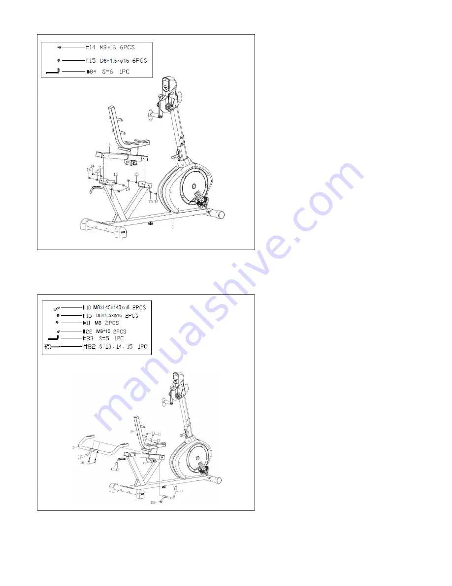
STEP 5
First, remove the preassembled 6
Hex
Pan Head Screws (No. 14)
and 6
Washers (No. 15)
from the
Slide Rail
(No. 4)
with
Allen Wrench (No. 84).
Then attach the
Slide Rail (No. 4)
to
the
Main Frame (No. 1)
with 6
Hex
Pan Head Screws (No. 14)
and 6
Washers (No. 15)
tightly using
Allen
Wrench (No. 84).
STEP 6
1. First, remove the preassembled 2
Hex Socket Cap Screws (No. 22)
from
the
Axle (No. 19).
Then attach the
Adjustment Handle (No. 8)
to the
Axle (No. 19)
, and secure tightly with
the 2
Hex Socket Cap Screws (No. 22)
using
Allen Wrench (No. 83)
. Make
sure the
Adjustment Handle (No. 8)
is
pointing up.
2. Set the
Handlebar (No. 3)
onto the
Seat Tube (No. 2)
, and secure tightly
with the 2
Square Neck Bolts (No. 10)
,
2
Washers (No. 15)
and 2
Ball Cap
Nuts (No. 11)
using
Spanner (No. 82)
.
Connect the 2
Pulse Wires (No. 41)
with the 2
Pulse Sensor Wires 1 (No.
42)
.
Summary of Contents for SF-RB4631
Page 3: ...2 EXPLODED DIAGRAM ...


