background image

20 


TREADMILL FUNCTIONS 


SAFETY LOCK FUNCTION: 

Removing  the 

Safety  Key  (No.  66)

  from  the  computer  console  while  the  treadmill  is  running  will 

cause  it  to  stop  immediately.  Once  the  treadmill  reaches  a  full  stop,  the  window  display  of  the 
computer will show  “- - -” and the treadmill will beep 3 times. To start the treadmill again, insert the 
magnet end of the 

Safety Key (No. 66)

 into the computer console and press the START button. 


POWER SAVE FUNCTION: 

When  the  treadmill  has  been  inactive  for  10  minutes,  it  will  enter  Power  Saving  Mode.  While  the 
treadmill  is  in  this  mode,  the  window  display  of  the  computer  will  be  turned  off.  To  turn  it  back  on, 
press any button.  
 

POWER ON: 

Flick the power switch to this symbol to turn on the treadmill. 
 

POWER OFF: 

Flick  the  power  switch  to  this  symbol  to  turn  the  treadmill  off  at  any  time.  This  includes  during 
exercise. 


SAFETY NOTE: 

We recommend that you maintain a slow speed at the beginning of a session and hold the handrails 
until you have become familiar with the treadmill.  
 
Insert the magnet end of the 

Safety Key (No. 66)

 into the computer console and attach the opposite 

end  (containing  the  safety  clip  on  it)  to  your  clothing  before  starting  your  workout.  To  end  your 
workout,  press  the  STOP  button  or  remove  the 

Safety  Key  (No.  66)

  and  the  treadmill  will  stop 

immediately. 


Summary of Contents for SF-T4400

Page 1: ...PORTANT Please retain owner s manual for maintenance and adjustment instructions Your satisfaction is very important to us PLEASE DO NOT RETURN UNTIL YOU HAVE CONTACTED US support sunnyhealthfitness c...

Page 2: ...the manufacturer 3 Never operate this treadmill if it has a damaged cord or plug if it is not working properly if it has been dropped or damaged or dropped into water Return this treadmill to a servic...

Page 3: ...lid flat level surface with a protective cover for your floor or carpet To ensure safety the equipment should have at least 8 feet 240CM of free space behind it and 2 feet 60CM on each side Do not pla...

Page 4: ...rgency use The machine will function only if the safety key is inserted into the computer console In case of emergency remove the safety key to immediately stop the belt and shut off the treadmill The...

Page 5: ...4 EXPLODED DIAGRAM...
Page 6: ...1 Upper Signal Wire 1 19 Side Rail 2 62 Middle Signal Wire 1 20 Running Belt 1 63 Lower Signal Wire 1 21 Motor Belt 1 64 Allen Socket Bolt M8 45 1 22 Console 1 65 DC Motor 1 23 Blue Cushion 2 66 Safet...

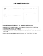
Page 7: ...n order for us to accurately identify the part s needed The model number found on cover of manual The product name found on cover of manual The part number found on the EXPLODED DIAGRAM and PARTS LIST...

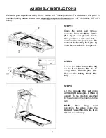
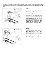
Page 8: ...d ensure that you have a work area that is clean and has adequate space Do not cut the Packing Belt No C until the assembly is complete STEP 3 Lift the Console No 22 along with Upright Tubes No 4 No 5...

Page 9: ...ure using Allen Wrench No 12 Next tighten 2 already preassembled Allen Socket Bolts No 42 located on the inner sides of the left and right handlebar STEP 4 Support the Upright Tubes No 4 No 5 with you...

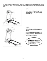
Page 10: ...ness com or 1 877 90SUNNY 877 907 8669 STEP 7 You may now cut the Packing Belt No C Insert the Safety Key No 66 into the magnetic area of the Console No 22 The assembly is complete IMPORTANT NOTE You...

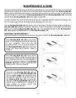
Page 11: ...itable tightness for the Running Belt No 20 is pulled out 50 75mm from the Running Board No 70 CENTERING THE RUNNING BELT Place the treadmill on level ground and set it at 3 5mph to check if the Runni...

Page 12: ...70 Use a rag to thoroughly wipe the lubricant over the Running Board No 70 Repeat this process for the other side 2 The moving parts should turn freely and quietly Abnormal of moving parts will affec...

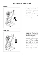
Page 13: ...tube you will hear a clicking sound Before lowering the Main Frame No 2 ensure that the space directly underneath it is clear of any objects Hold the Main Frame No 2 at position A with one hand Next u...

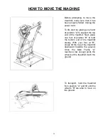
Page 14: ...top end of the treadmill Next place one foot at position B to hold the bottom end of the treadmill steady With your foot at B slowly tilt the top of the treadmill downward towards the ground Once the...

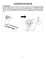
Page 15: ...There are three holes located on the Adjustable Foot Pad No 29 To adjust the level of incline remove the 2 Fixing Pins No 7 from the left and right side Align the holes of the Adjustable Foot Pad No 2...

Page 16: ...and has a grounding plug that looks like the plug illustrated in sketch A Make sure that the product is connected to an outlet having the same configuration as the plug No adapter should be used with...

Page 17: ...SPEED BUTTONS 2 4 6 MPH NOTE The maximum speed on this treadmill is 9 MPH CONTROL FUNCTIONS 1 Press the Speed Button to reduce the running speed 2 Press the Speed Button to increase the running speed...

Page 18: ...nt down from the setting data to 0 00 When it reaches 0 00 the machine will stop smoothly and display End and automatically reset to the initial setting after 5 seconds CALORIES Displays the number of...

Page 19: ...ill increase or decrease the speed continually 2 4 6 QUICK SPEED BUTTONS These buttons are preset to 2 4 or 6 MPH speeds for convenience INTERVAL PROGRAMS P1 P9 Press the PROGRAM button to select an i...

Page 20: ...e handles with both hands and hold them for 3 seconds The window will display your Body Mass Index The Body Mass Index is used to test the relation between your height and weight It is only for refere...

Page 21: ...n this mode the window display of the computer will be turned off To turn it back on press any button POWER ON Flick the power switch to this symbol to turn on the treadmill POWER OFF Flick the power...

Page 22: ...nausea Get to know your treadmill Before attempting to use the treadmill take some time to stand alongside and familiarize yourself with the controls Once you get on you can stand with your feet on th...

Page 23: ...e computer and bottom control board not properly connected Check wire connections from the computer to the control board Transformer is damaged If the transformer has become damaged contact customer s...

Reviews: