6
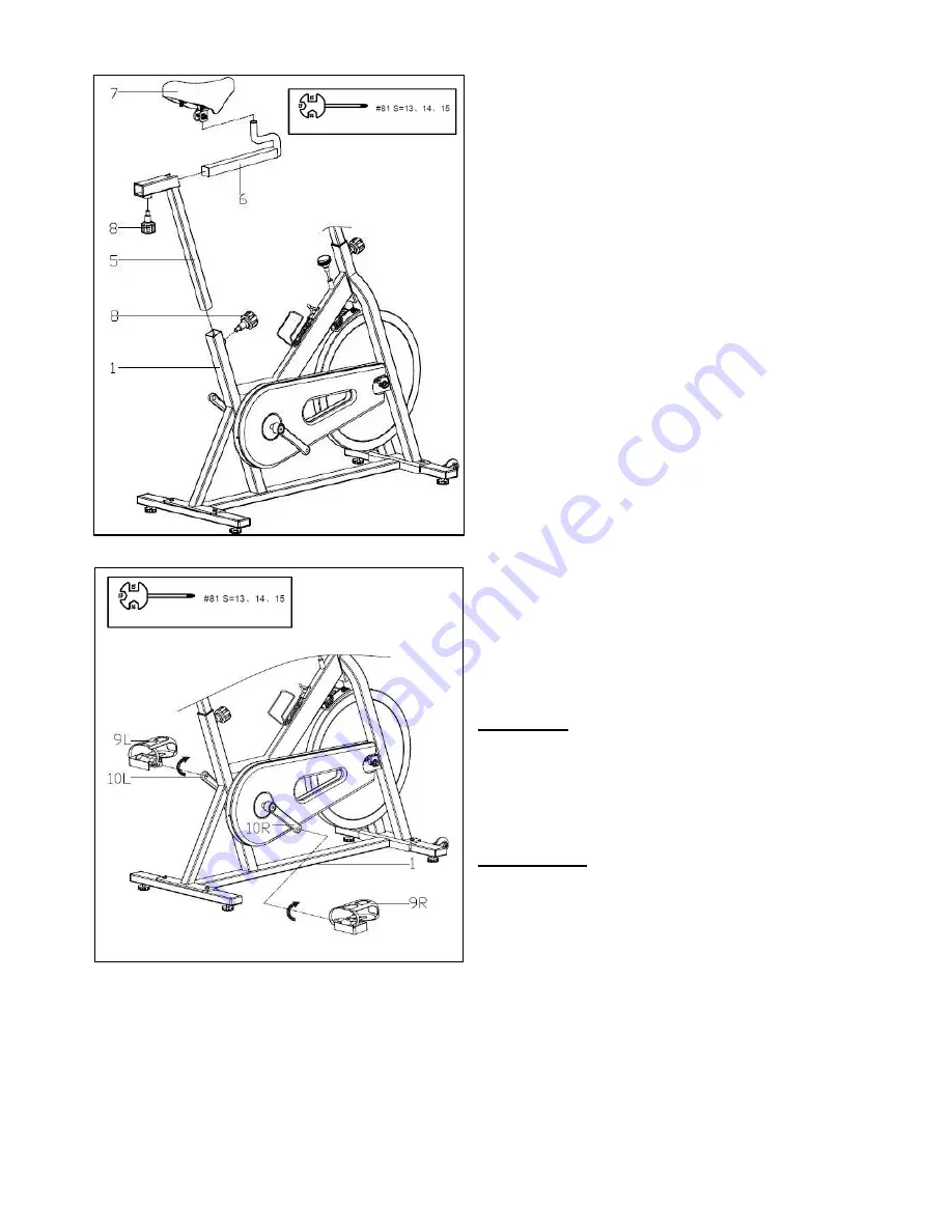
STEP 3:
Lock the
Seat (No. 7)
onto the
Seat Slider
(No. 6)
tightly. Tighten and secure with
Spanner (No. 81)
.
Adjust the seat to the
desired position by sliding it on
Seat Slider
(No. 6)
then lock the
Seat Slider (No. 6)
on
the
Seat Post (No. 5)
with
Pop-Pin Knob
(No. 8)
. Insert the
Seat Post (No. 5)
to the
rear upright tube of
Main Frame (No. 1)
then adjust the height and secure with
Pop-
Pin Knob (No. 8).
Note:
Both
the
fore/aft
and
up/down
adjustments of the Seat (No. 7) need to be
secured with Pop-Pin Knob (No. 8). Ensure
the Seat (No. 7) is locked onto the Seat Slider
(No. 6) before adjusting the height.
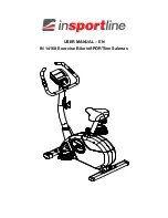
STEP 4:
Attach the
Pedal (No. 9L/R)
to their
corresponding
Crank (No. 10 L/R)
. Before you
begin, immobilize the crank arms by turning the
brake knob all way to the right.
Left Pedal:
The
Left Pedal (No. 9L)
is marked
L for left side. Align the
Left Pedal (No. 9L)
to
the
Left Crank (No. 10L)
at 90 degrees and
insert the pedal. Turn
counter-clockwise
as
tightly as you can with your hand then secure
with
Spanner (No. 81).
Right Pedal:
The
Right Pedal (No. 9R)
is
marked R for right side. Align the
Right Pedal
(No. 9R)
to the
Right Crank (No. 10R)
at 90
degrees and insert the pedal. Turn
clockwise
as tightly as you can with your hand then
secure with
Spanner (No. 81).
Assembly is complete!
Summary of Contents for SF-B1001S
Page 3: ...2 EXPLODED DIAGRAM...


