background image


I

II

III


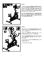
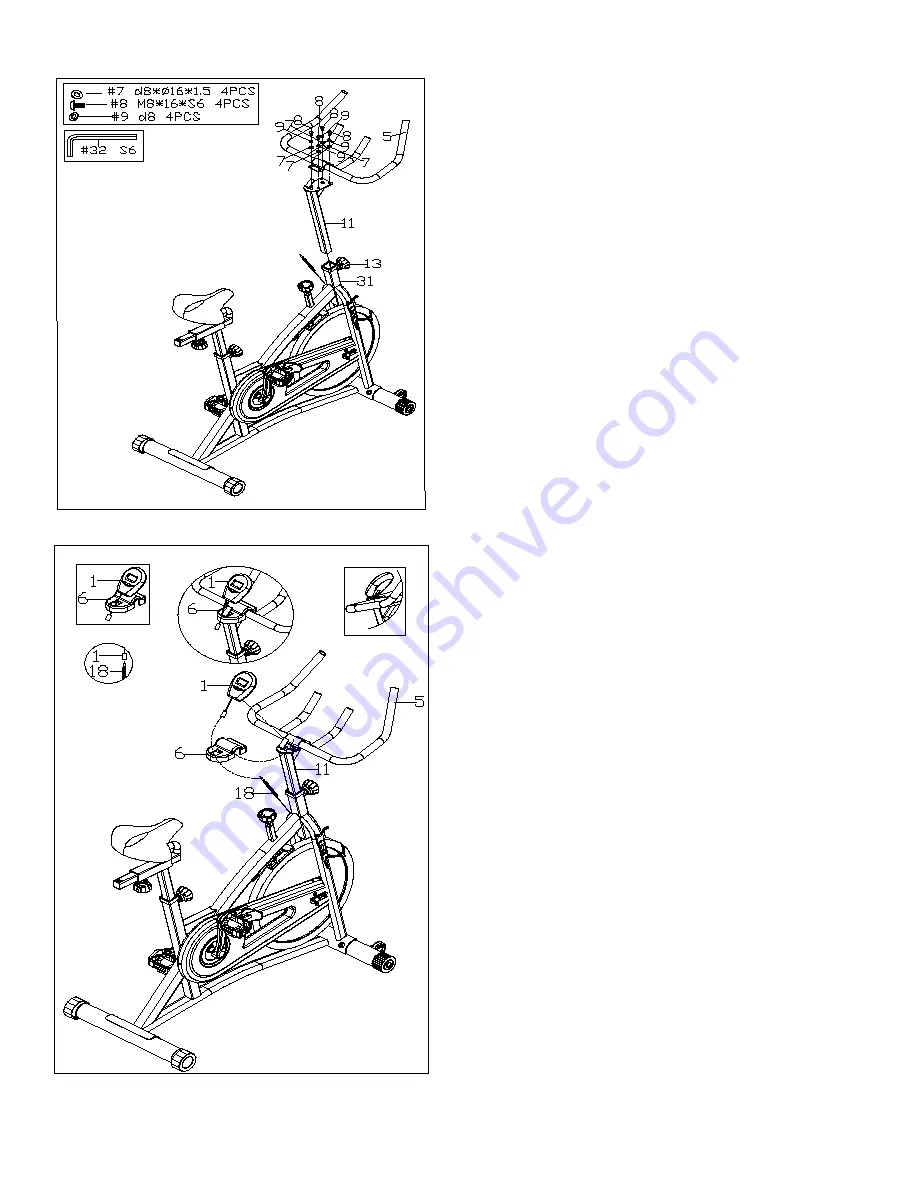
STEP 3: 

 
Loosen and pull out the 

Adjustment


Knob (No. 13)

Insert the 

Handlebar Post (No. 11)

 into the sleeve 

located on the front of the 

Main Frame (No. 31)

Adjust the 

Handlebar Post (No. 11)

  to the desired 

position, re-insert and tighten the 

Adjustment Knob 

(No. 13)

 to secure the post in place. 

 
Attach the 

Handlebar (No. 5)

 to the 

Handlebar Post 

(No. 11)

 using 4 

Screws (No. 8)

, 4 

Spring Washers 

(No. 9)

 and 4 

Washers (No. 7)

. Tighten and secure 

with 

Allen Wrench (No. 32)

.  


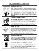
STEP 4: 
 

Insert the link wire of the 

Computer (No. 1)

 into the 

middle hole of the 

Handlebar Cover (No. 6)

  as 

shown in 

(Picture I)

 
Attach the 

Handlebar Cover (No. 6)

  to the 

Handlebar (No. 5)

 as shown in 

(Picture II)

.  

 
Attach the 

Computer (No. 1)

 to the bracket located 

on the 

Handlebar Post (No. 11)

  as shown in 

(Picture III)

.  

 
Connect the link wire of the 

Computer (No. 1)

 to the 

Inductor (No. 18)

.  

 
The Assembly is complete! 
 

Summary of Contents for SF-B1421

Page 1: ...ANUAL IMPORTANT Please retain owner s manual for maintenance and adjustment instructions Your satisfaction is very important to us PLEASE DO NOT RETURN UNTIL YOU HAVE CONTACTED US support sunnyhealthf...

Page 2: ...e equipment The equipment is designed for adult use only 4 Use the equipment on a solid flat level surface with a protective cover for your floor or carpet To ensure safety the equipment should have a...

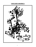
Page 3: ...2 EXPLODED DRAWING 1...

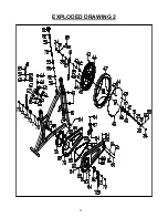
Page 4: ...3 EXPLODED DRAWING 2...

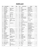
Page 5: ...5 1 44 3 5 2 16 Seat Slider 1 50 Inertia Axle 12 150 M12 1 0 1 17 Seat 1 51 Tension Knob M10 58 48 1 18 Inductor 1 52 Nut M10 H5 5 S17 2 19 Water Bottle Holder 1 53 Brake Rod 10 200 M10 15 M 6 7 M10 9...

Page 6: ...t Nylon Nut 9 16 20 H8 S19 1 86 Washer d6 16 1 5 2 77 Right Nylon Nut 9 16 20 H8 S19 1 87 Blanking Plate 1 78 Bushing 20 20 62 1 88 L R Pedal YH 76X 9 16 2 HARDWARE PACKAGE Ordering Replacement Parts...

Page 7: ...panner No 33 to hold the bolt of the pedal then attach Right Nylon Nut No 77 counter clockwise into the thread end of the Right Pedal No 88R Secure with Spanner No 57 Remove pre assembled 2 Screws No...

Page 8: ...the Handlebar Post No 11 using 4 Screws No 8 4 Spring Washers No 9 and 4 Washers No 7 Tighten and secure with Allen Wrench No 32 STEP 4 Insert the link wire of the Computer No 1 into the middle hole...

Page 9: ...nd With the wheels on the ground you can transport the bike to the desired location with ease ADJUSTING THE ANGLE OF SEAT Use Spanner No 33 to unscrew the nut under the saddle Adjust the saddle to the...

Page 10: ...VALUE SETTING Press the MODE when the indicator arrow is on the chosen value Time Speed Distance Calories Scan and then release Once locked only the selected function will be displayed FUNCTIONS TIME...

Page 11: ...ve damage 3 Clean and lubricate pop pin assemblies Pull on the pin and spray a small amount of lubricant onto the shaft 4 Tighten the seat hardware to make sure the seat is level and centered 5 Brush...

Reviews: