8
ADJUSTMENTS & USAGE GUIDE
11
13
ADJUSTING THE HEIGHT
Loosen and pull out the [seat height]
Adjustment Knob (No. 13)
to
adjust
the height of the saddle. You may also slide the seat forward or backwards
by loosening and pulling out the [seat]
Adjustment Knob (No. 13)
on the
Seat Slider (No. 16).
You may adjust the height of the handlebar by using
the [handlebar]
Adjustment Knob (No. 13).
When making adjustments, you
will see a limit on the saddle post, seat slider and handlebar post. Do NOT
lift the posts passed this mark. Always check the
Adjustment Knob (No.
13)
to ensure that they are fully secure when you finish making an
adjustment.
MOVING THE BIKE
To move the bike, first ensure that the handlebar is properly secured. If the
handlebar is loose, tighten the
Adjustment Knob (No. 13)
to secure it. Next,
stand at the front of the bike so that you’re directly in front of the handlebar.
Firmly grab and hold each side of the
Handlebar (No. 5)
, place one foot on
the front stabilizer and tilt the bike towards you until the transportation
wheels on the front stabilizer touch the ground. With the wheels on the
ground, you can transport the bike to the desired location with ease.
ADJUSTING THE ANGLE OF SEAT
Use
Spanner (No. 33)
to unscrew the nut under the saddle. Adjust the
saddle to the desired angle and re-install and secure the nut. Check the nut
periodically to ensure that it is tight and secure. Use the
Spanner (No. 33)
to tighten when necessary.
Note: In order to properly tighten the seat, it is important to note that you will
need two
Spanner (No. 33)
(1 for each side) and will need to tighten the nut
on each side simultaneously working in opposite direction of each other.
ADJUSTING THE TENSION & EMERGENCY STOP
Adjusting tension by rotating the
Tension Knob (No. 51)
clockwise to
increase the level of resistance. Rotate the knob counter-clockwise to
decrease the level of resistance. Push down on
Tension Knob (No. 51)
to
enforce the brake and stop the bike immediately.
ADJUSTING THE BALANCE
In order to achieve a smooth and comfortable ride, you must ensure that the
stability of the bike is secured. If you notice that the bike is unbalanced during
use, you should adjust the end caps located on the rear stabilizer. To do so,
simply rotate the
End Caps (No. 28)
located on the
Rear Stabilizer (No. 29)
until the bike becomes level with the floor surface.
Summary of Contents for SF-B1421
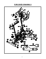
Page 3: ...2 EXPLODED DRAWING 1...
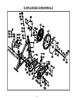
Page 4: ...3 EXPLODED DRAWING 2...


